
Correlating detected events with image data

Active Publication Date: 2013-06-11
NCR CORP
View PDF15 Cites 133 Cited by
  • Summary
  • Abstract
  • Description
  • Claims
  • Application Information

AI Technical Summary

Benefits of technology

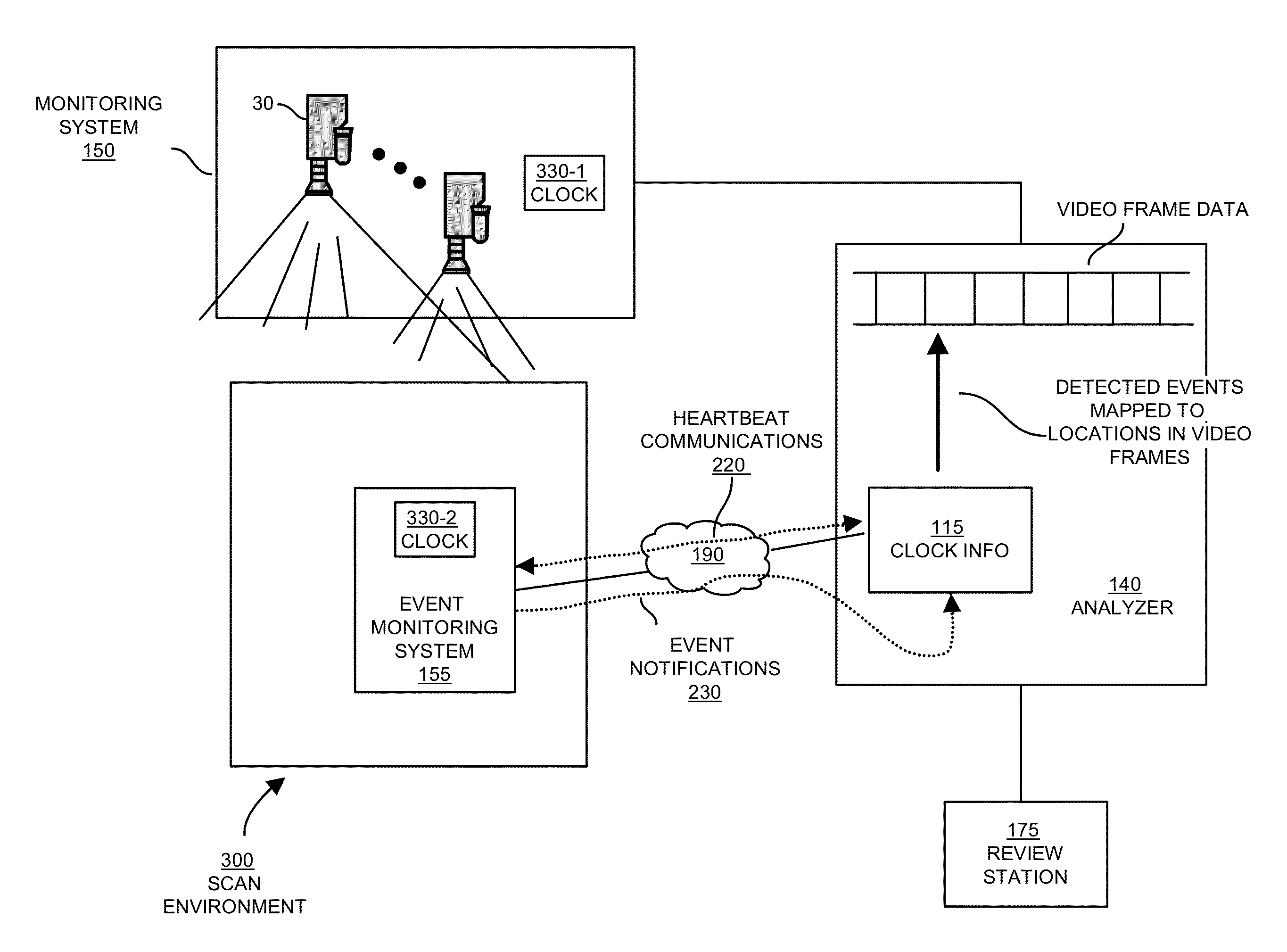
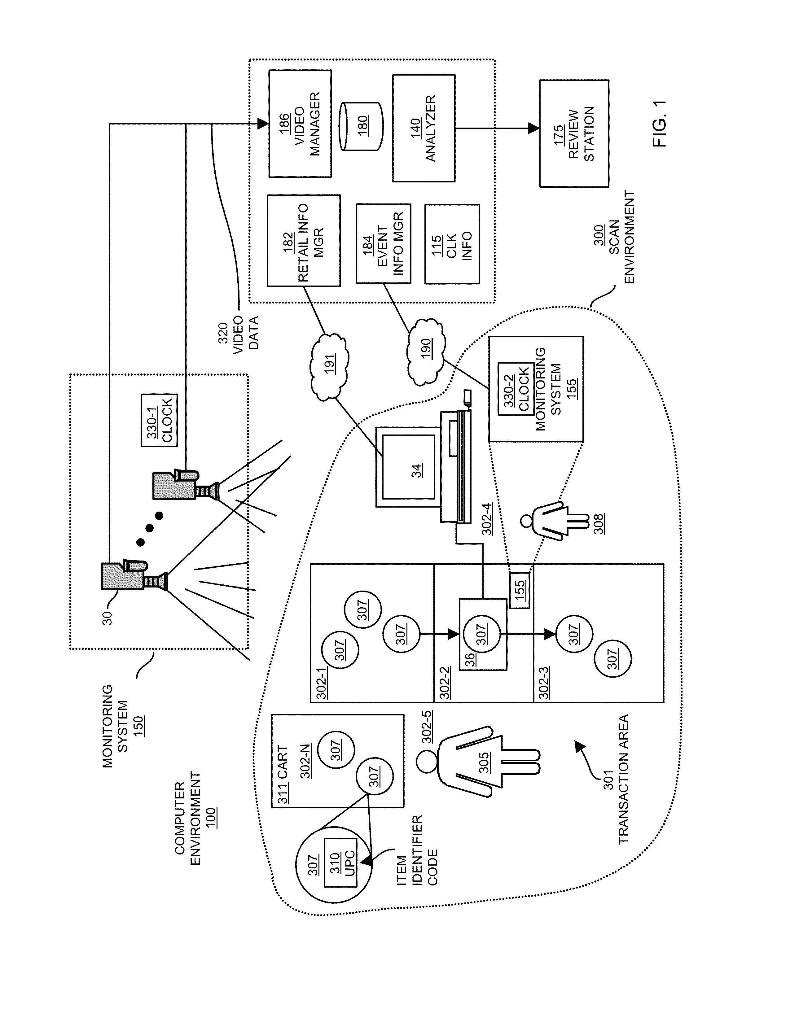
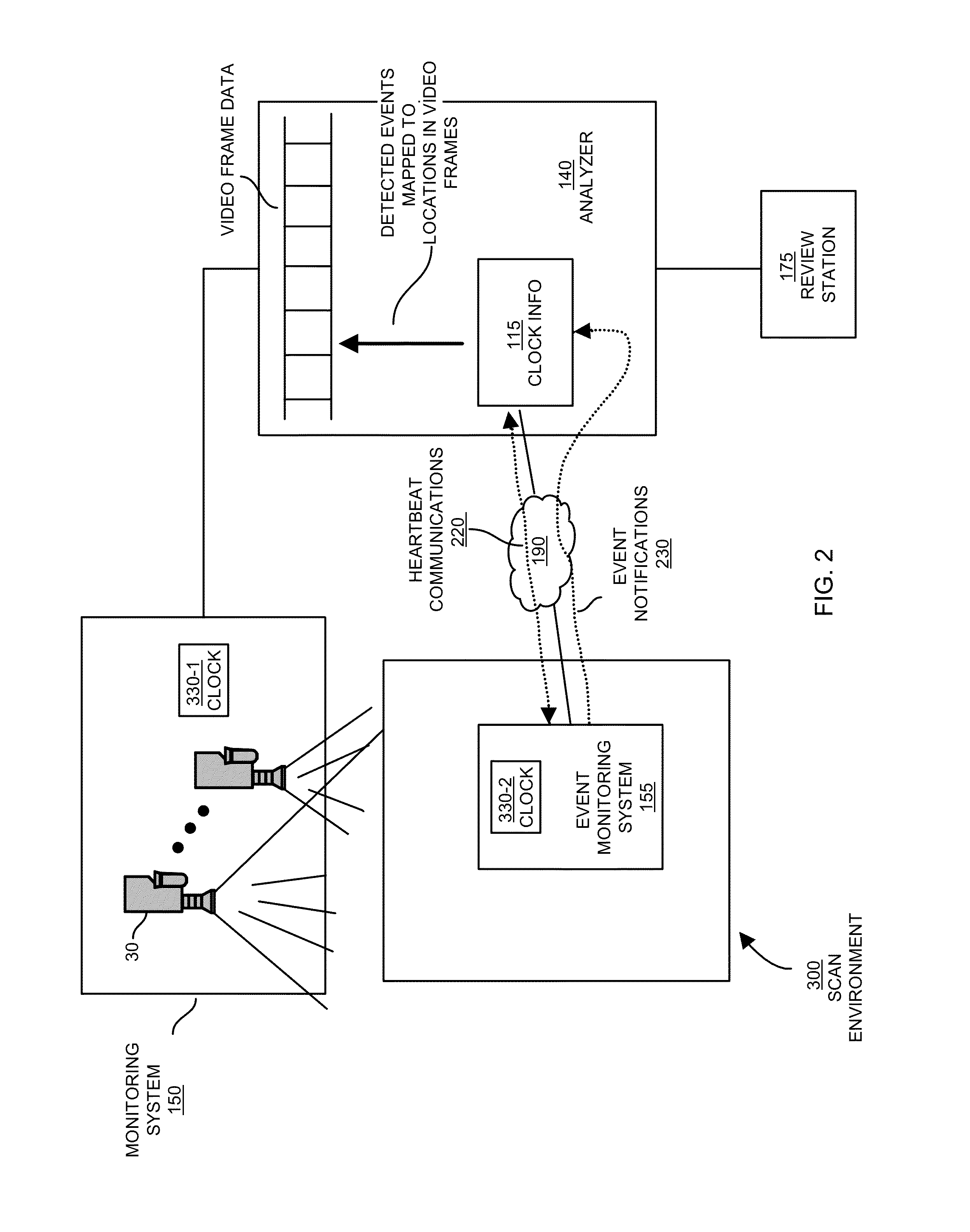
The patent discusses a system for detecting and reviewing activity in a retail environment. It uses a first monitoring system to capture video and associated timing information based on a first system clock. A second monitoring system, which is independent of the first system, detects events in the video and time stamps them based on a second system clock. The analyzer receives the time-stamped events from the second monitoring system and uses heartbeat signals to calculate a time skew between the first and second clocks. This allows the analyzer to accurately identify the time or location in the video when an event occurred. The system can also identify specific locations or times where incidents such as theft or loss of inventory occur at a point-of-sale transaction terminal.

Problems solved by technology

These conventional systems that provide for purchase of items using an automated item identification systems such as a scanner suffer from a variety of deficiencies.
In particular, operation of such systems can be compromised, either knowingly or unknowingly, by an operator in a manner that allows a customer to receive possession of one or more items without paying for them.
For example, such scanning systems are susceptible to “pass-throughs,” also know as “sweethearting” in which an operator purposefully or accidentally fails to scan an item as that item moves through the transaction area.
Retail chains lose millions of dollars a year to operator error or fraudulent activity of this nature.
In another fraudulent example known as label switching, the operator causes the POS system to scan an item that is different that the item being passed through the scanning area during the transaction.
In such cases, a customer or operator may replace a UPC label of an original and often expensive item with a UPC label for another less expensive item.
The conventional scan-gap detection method is widely regarded to be impractical, as scan-gaps have been found to be a “noisy” measure at best.
This is due to the fact that perfectly legitimate scan-gaps may vary widely due to delays such as those caused by weighing of produce, manual entry of unlabeled or un-scannable goods, and rescanning of items that did not get scanned on the first pass.
As a result, scan-gaps are not a dependable metric for determining improper activity.
Thus, conventional systems that attempt to use scan gaps as a method for detecting fraudulent activity are prone to problems.
Discrepancies between the video data as captured by a security camera and the data from the registers may indicate that fraudulent activity may be taking place.
One of the challenges associated with correlating video data with a confirmation by the scanner that the item was properly scanned is that the two independent sources generating this information need to be synchronized.
Such an option is impractical if not impossible in real world applications.
Given the difference in clocks, it is often difficult to manually correlate scan data from a register with video surveillance footage.
In other cases, the conventional scanner may not even provide any indication whatsoever when an item was scanned during checkout.
However, it is often the case that the POS register will not send information in a timely manner across a network when a scan occurs.
In other words, there can be a substantial latency associated with a time of identifying that a scan takes place at scanner system and a time of sending a message over a network to indicate occurrence of the scan.
Accordingly, by itself, monitoring network traffic and time-stamping detected events may not be useful.
Furthermore, even if a POS communicates across a network at the time of each scan, due to the closed nature of such a respective communication system, it may be difficult for a monitoring system to decipher contents of the network messages and generate notification at an appropriate time.
Accordingly, in this last instance, it can be difficult to detect which data produced by a scanner of other device is useful for reporting of an event.
However, such integration is often costly and time consuming.
And, since there are many POS manufacturers in use today, this strategy could become prohibitively expensive.
As discussed above, reconciling item scan data with frames of corresponding video may be difficult or impossible since the system clocks associated with a point-of-sale transaction (or different nodes in a network) are typically not synchronized with system clocks of the surveillance camera used to gather the video.
Because the clocks are not synchronized as discussed above, it is typically difficult for a reviewer to accurately map events associated with scanning of an item at a scanner to corresponding times or locations in the video.

Method used


Image

  • Correlating detected events with image data
  • Correlating detected events with image data
  • Correlating detected events with image data

Examples


Embodiment Construction

[0063]According to one embodiment, an analyzer system receives communications from a first monitoring system and a second monitoring having different system clocks. For example, a first monitoring system produces the video based on a first clock. The second monitoring records occurrence of events based on a second clock. The first clock and second clock drift apart over time but can be occasionally adjusted so they are approximately synchronized with each other.

[0064]The analyzer system according to embodiments herein can be configured to receive, from the first monitoring system, video of an item being scanned at a scanner system. The analyzer also can be configured to detect, via a communication from a second monitoring system, an occurrence of at least one event associated with scanning of the item at the scanner system. Event notifications from the second monitoring system can be sent to the analyzer over a variable latency network. Thus, there may be a considerable time delay b...


PUM


Abstract

According to one configuration, a computer environment includes a first monitoring system, a second monitoring system, and an analyzer. The first monitoring system produces video of an item being entered into a point of sale system. The second monitoring system monitors events associated with entering of the item into the point of sale system. The analyzer detects, via a communication from the second monitoring system, an occurrence of at least one event associated with entering of the item. Based on communication, the analyzer correlates the at least one event to a particular time in the video when the at least one event occurred.

Description

RELATED APPLICATIONS[0001]This application is related to and claims the benefit of earlier filed U.S. Provisional Patent Application Ser. No. 61 / 143,544 entitled “SYNCHRONIZING POINT OF SALE DATA EVENTS WITH VIDEO,” filed on Jan. 9, 2009, the entire teachings of which are incorporated herein by this reference.[0002]This application is a continuation in part and claims priority to earlier filed U.S. patent application Ser. No. 12 / 328,585 entitled “ANONYMIZATION AND SYNCHRONIZATION BASED ON USE OF PROTECTED CONTENT,” filed on Dec. 4, 2008, the entire teachings of which are incorporated herein by this reference.BACKGROUND[0003]Retail establishments commonly utilize point of sale or other transaction terminals, such as cash registers, to allow customers of those establishments to purchase items.[0004]As an example, in a conventional department store, supermarket or other retail establishment, a customer collects items for purchase and places the items in a shopping cart, basket, or simp...

Claims


Application Information

Patent Timeline
IPC IPC(8): H04N7/18H04N9/475
CPCH04N7/18G07G1/0081
Inventor KUNDU, MALAYMIGDAL, JOSHUASRINIVASAN, VIKRAMFARROW, MATTHEW
Owner NCR CORP
Learn More