Electric- or magnetic-field based detection of when electrode pads have been handled or removed from their package

a technology of magnetic field and electrode pads, applied in the field of electrodes, can solve the problems of wasting precious time and taking much longer, and achieve the effect of accurately advancing the voice prompts

Active Publication Date: 2013-06-11
KONINKLIJKE PHILIPS ELECTRONICS NV
View PDF10 Cites 0 Cited by
  • Summary
  • Abstract
  • Description
  • Claims
  • Application Information

AI Technical Summary

Benefits of technology

[0013]As mentioned previously, correct and timely pad placement is essential to the efficacy of the shock. By sensing that the pads are being physically handled and manipulated by the user, the AED can determine that the previous action of calling 911 and removing the clothes has been completed. In this way, with no further button presses required of the user, the AED will immediately cease repeating its “Remove all clothes from the patient's chest” prompt and begin repeating the new prompt, “Look carefully at the pictures on the first pad. Remove the pad from the release liner and apply it exactly as shown in the picture.” This invention allows the AED to advance to the next prompt when, and only when the user is ready to progress to the next step, without additional input from the user.
[0014]Advantageously, the present invention provides a solution to accurately advance the voice prompts between two very critical actions: removing the clothes from the patient's chest and applying the pads to the patient's chest.
[0019]The present invention is directed to an alternative or additional method for detecting the handling or removal of electrode pads from their package that functions effectively no matter how slowly or gently the pads are handled or removed, because the present method detects the event of pad handling / removal based on the distance between the pads including their lead wires and a conductor embedded within the package. By means of an alternating current, an electric field is established between the conductor, as one plate of a capacitor, and the pads and wires as the other plate of the capacitor. Distance between the capacitor plates is sensed to determine when the pads have been handled or removed. Advantageously, the hardware for implementation is low in cost.

Problems solved by technology

For example, removing the clothes to bare the patient's chest might be a quick process if the patient is only wearing a tee-shirt, but will take much longer if there are multiple layers that need removing or cutting away.
The challenge lies in how the AED detects when the current action has been completed.
If the button is not pressed, the voice prompts do not proceed and precious time is lost while the user tries to determine the cause of the delay.

Method used


Image

  • Electric- or magnetic-field based detection of when electrode pads have been handled or removed from their package
  • Electric- or magnetic-field based detection of when electrode pads have been handled or removed from their package
  • Electric- or magnetic-field based detection of when electrode pads have been handled or removed from their package

Examples


Embodiment Construction

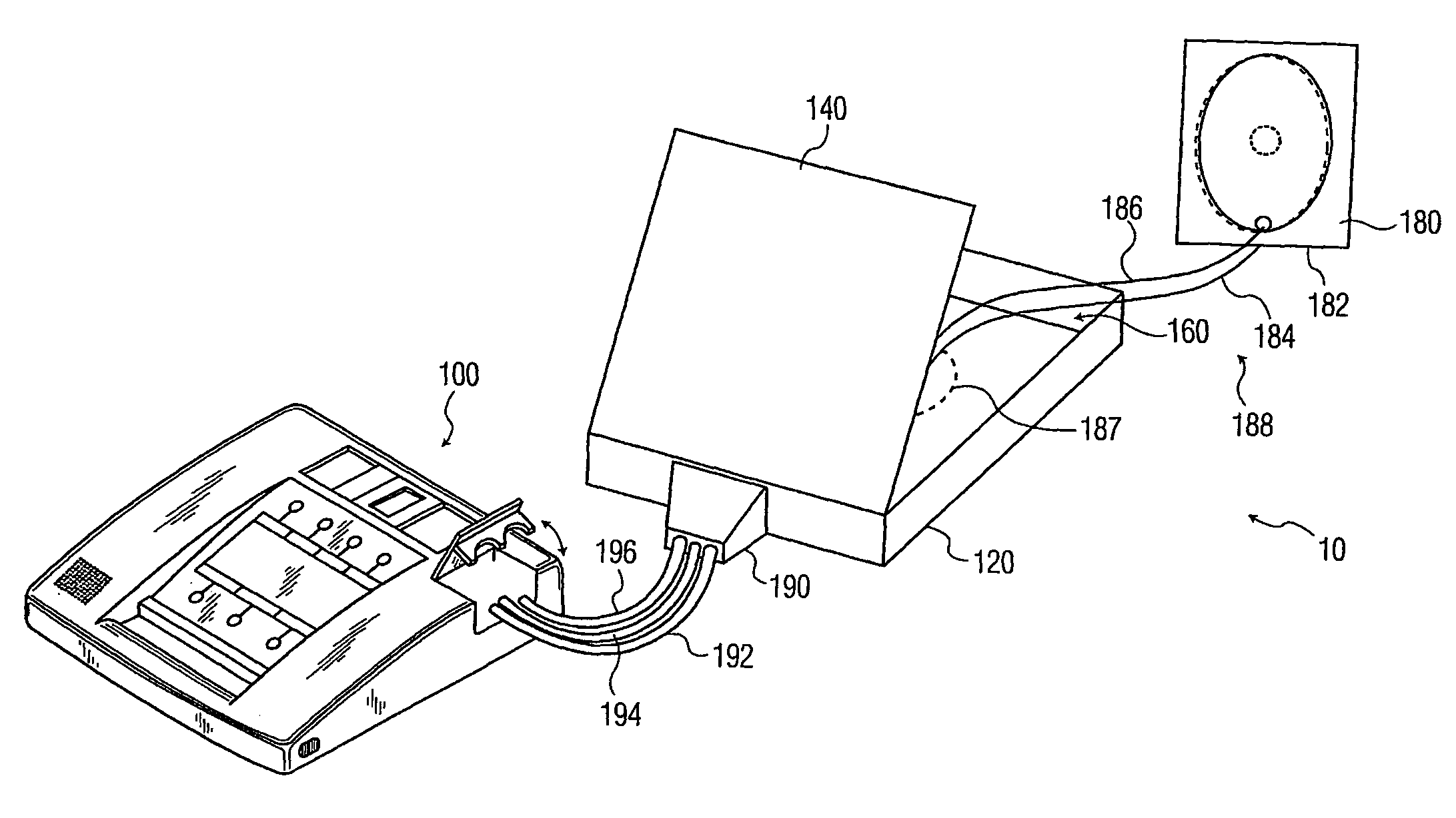
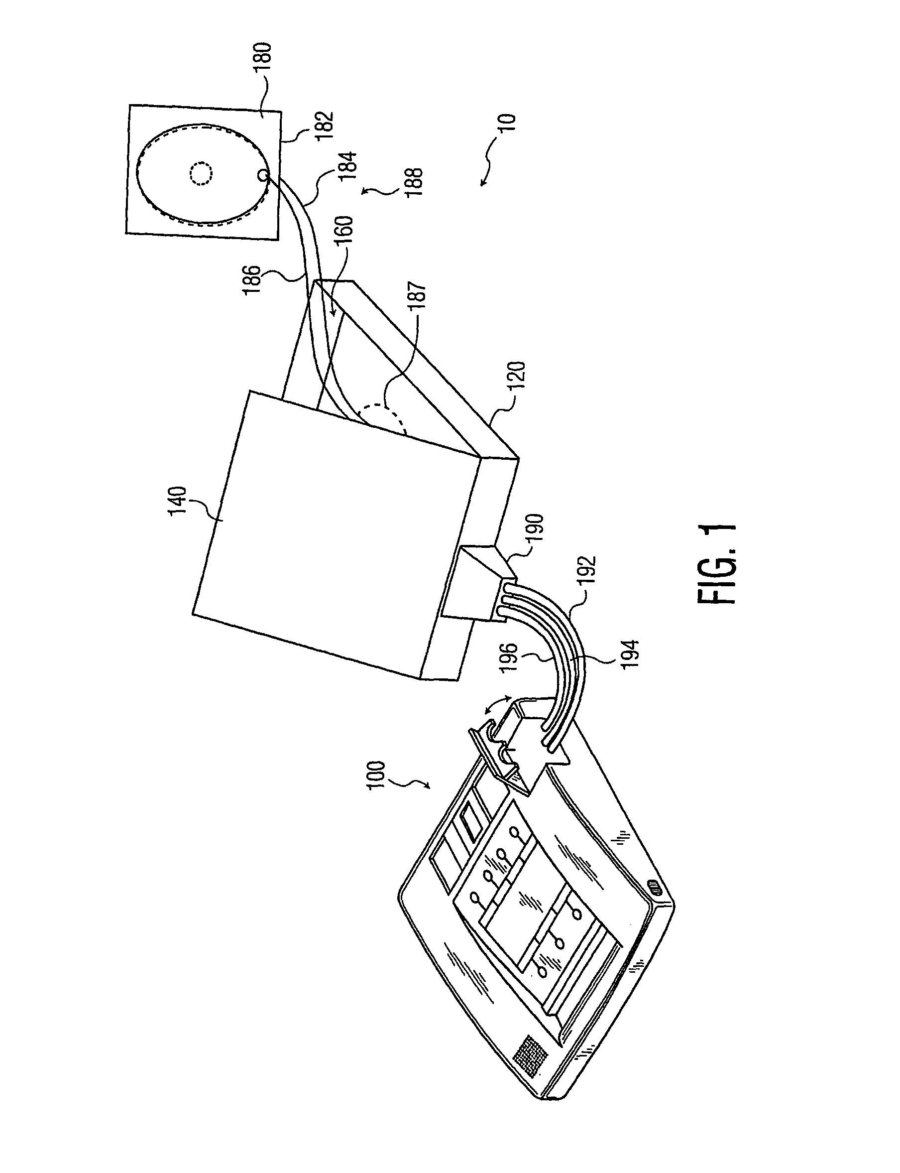
[0027]FIG. 1 portrays an exemplary defibrillation system 19 of the present invention including a defibrillator 100 and a rigid cartridge 120 having a lid 140 shown in the open position. The cartridge 120 further has, defined in part by the lid 140, an electrode compartment 160 in which a pair of electrode pads 180, 182 (the second pad 182 being obscured by the visible one 180) may be stored. The pads 180, 182 have respective lead wires 184, 186 and typically each have on one surface a skin-adhesive, electrically conductive layer such as hydrogel, the hydrogel layers sandwiching an electrically non-conductive release layer. Openings may be provided in the release layer, as discussed in the '478 publication, to provide a pathway for the flow of electric current between the electrode pads 180, 182. An electrical conductor, such as metal foil, serving as one plate 187 of a capacitor is embedded in the bottom of the cartridge 120. The electrode pads 180, 182 together with their lead wire...


PUM


Abstract

Handling or removal of a pair of defibrillator electrode pads from their package is detected in order to effectively time the issuance of prompts to guide the user. One plate of a capacitor is embedded in the package, the electrode pads and lead wires serving as the other plate. Impedance across the capacitor in an alternating current circuit is monitored to detect an increase in the distance between the pads and the package. The impedance level is determined, in a low-cost hardware solution, by rectifying and then integrating an output voltage of the capacitor to produce a voltage signal whose magnitude attenuates as the pads are handled or removed. In one embodiment, the above methodology is time-division multiplexed with an alternative process that identifies handling or removal based on pad-to-pad impedance. In a further embodiment, the capacitive configuration is replaced with an inductive one.

Description

CROSS REFERENCE TO RELATED APPLICATION[0001]This application claims the benefit of U.S. provisional application Ser. No. 60 / 483,198 filed Jun. 27, 2003, which is incorporated herein.BACKGROUND OF THE INVENTION[0002]1. Field of the Invention[0003]The present invention relates to electrodes, and, more particularly, to detecting movement of electrodes.[0004]2. Discussion of the Prior Art[0005]In the US alone, over 350,000 people die annually from Sudden Cardiac Arrest. Many of these victims have no prior warning of heart disease, and 70% die outside the hospital. The only treatment for an SCA victim is to provide an immediate, high-energy electric shock through the heart. Minimizing the time to first shock is critical since, for every minute after 4 minutes, the chances of resuscitation decrease by 10%. If a shock is not applied within 10 minutes, the chances of resuscitation are almost zero.[0006]U.S. Pat. No. 5,700,281, issued on Dec. 23, 1997, hereinafter “the '281 patent,” the enti...

Claims


Application Information

Patent Timeline
Patent Type & Authority Patents(United States)
IPC IPC(8): A61N1/00A61N1/04A61N1/08A61N1/39
CPCA61N1/0408A61N1/0492A61N1/08A61N1/3931A61N1/046A61N2001/37294
Inventor ROBERTS, DOUGLASHANSEN, KIM
Owner KONINKLIJKE PHILIPS ELECTRONICS NV
Why Eureka
Try Eureka