Cutting device

Active Publication Date: 2012-03-08
CLAAS SELBSTFAHRENDE ERNTEMASCHINEN GMBH
View PDF20 Cites 5 Cited by
  • Summary
  • Abstract
  • Description
  • Claims
  • Application Information

AI Technical Summary

Benefits of technology

[0014]The problem addressed by the present invention is therefore that of providing a cutting device of the initially stated type that enables the shear bar to be moved toward

Problems solved by technology

The cutting blades become worn during operation.
The chopping process is thereby impaired.
If the distance is too great, a portion of the incoming material may not be cut completely, and greater cutting forces may be required.
If the distance is too small, there is a risk in particular that the cutting blades and shear bar will touch each other, which can result in material damage and even cause material and/or machine elements to come loose, which is hazardous.
Therefore, there is a need to be able to precisely adjust the distance between the shear bar and the cutting tool, which poses a design challenge due to the high cutting forces that occur during operation.
Due to the above-mentioned high forces acting on the shear bar during operation, said shear bar is mounted in a rigid manner such that it cannot be adjusted without inducing a reaction.
W

Method used


Image

  • Cutting device
  • Cutting device
  • Cutting device

Examples


Embodiment Construction

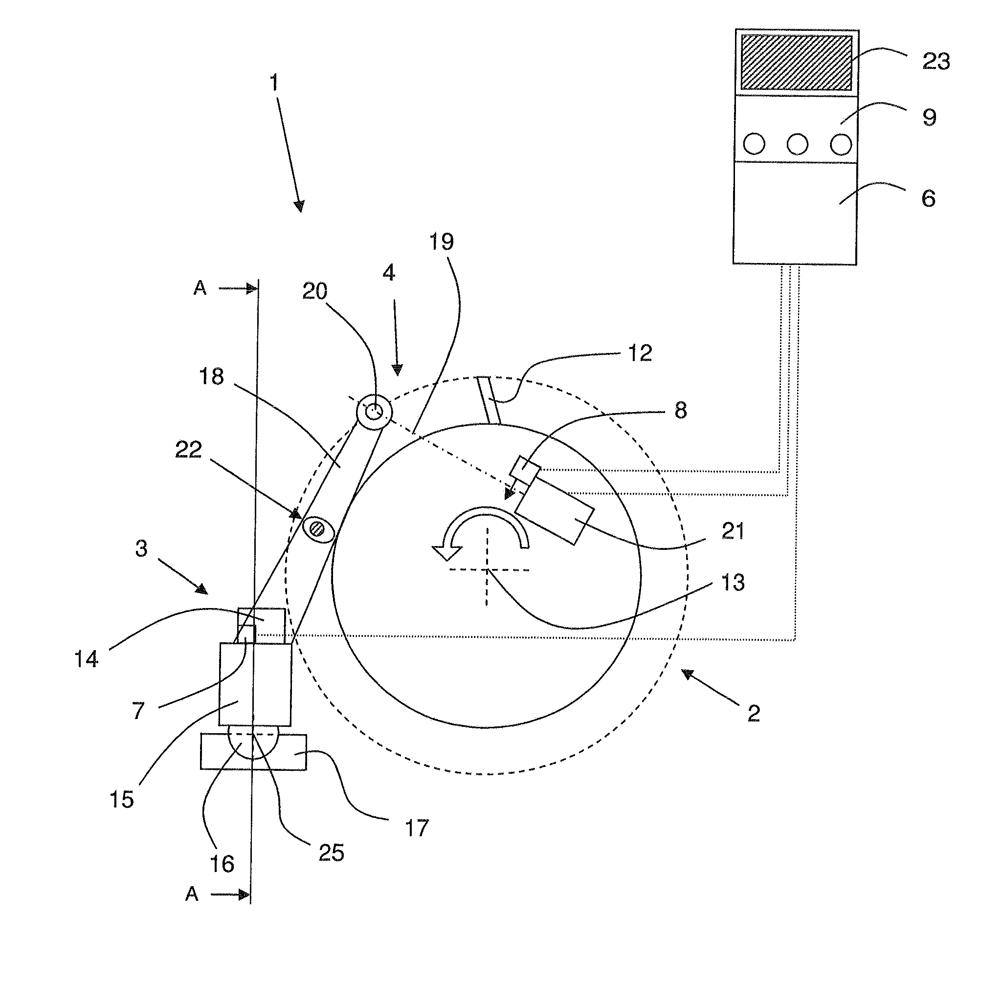
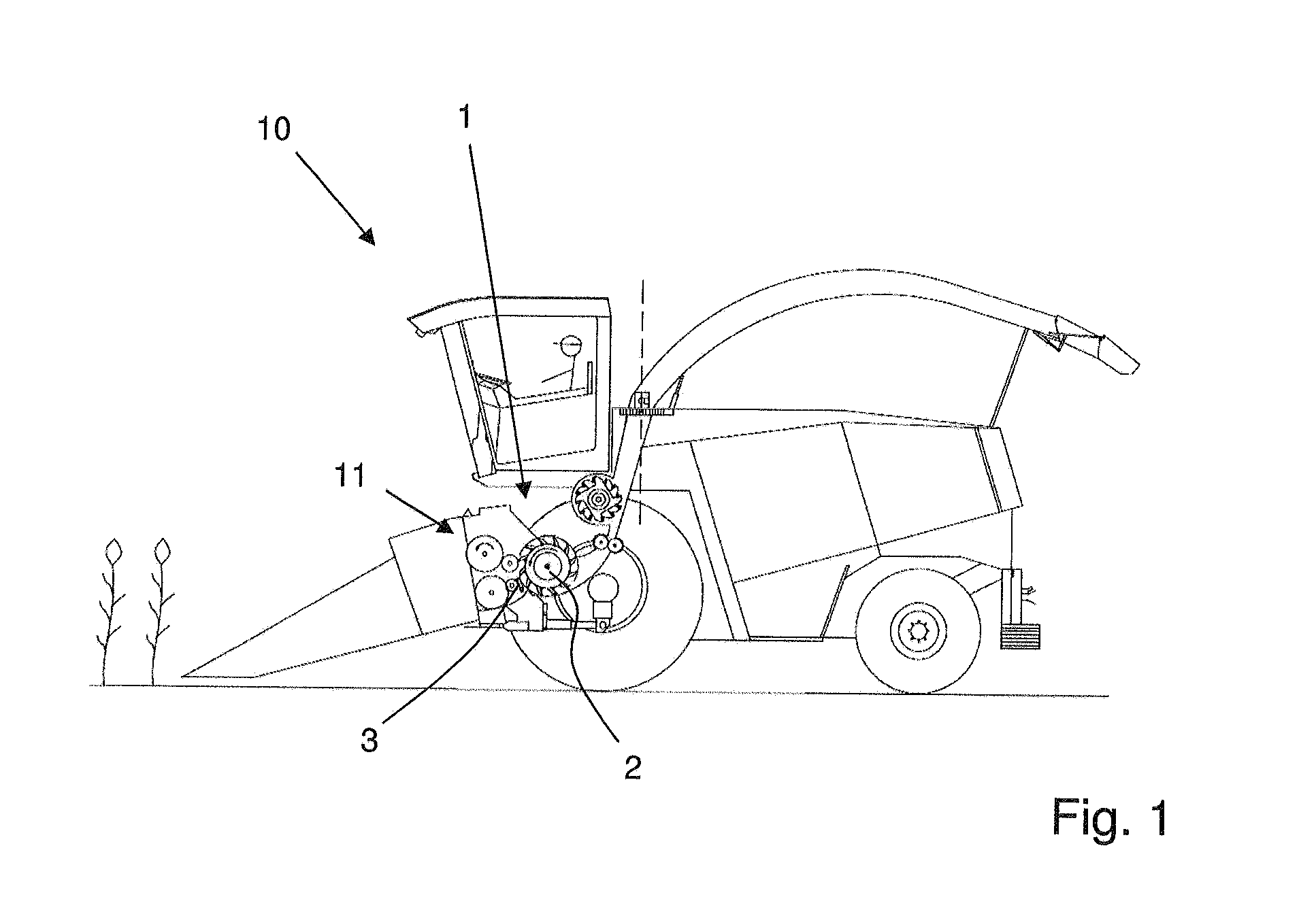
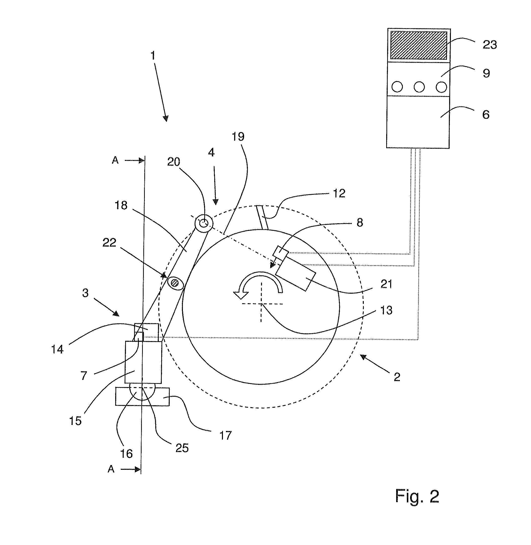
[0032]FIG. 1 shows a forage harvester 10 as an example. Forage harvester 10 is designed as a self-propelled harvesting machine having a front axle and a rear axle, and is suitable for driving across a field to harvest the plant crop which is indicated. During harvesting operation, forage harvester 10 cuts the plant crop from the field using a front attachment, which is not described in greater detail, and directs it to an intake conveyor mechanism 11 which comprises, inter alia, two pair of compression rollers which compress the harvested material. Next, the harvested material is conveyed to a cutting device 1 (“chopping assembly”) which mainly comprises a rotating cutting cylinder 2 and a shear bar 3 which is stationary relative thereto. The design and mode of operation of cutting device 1 are explained in greater detail with reference to FIGS. 2 and 3. The crop is fragmentized as it passes through cutting device 1, thereby enabling it to be conveyed through a conveyor chute which ...


PUM


Abstract

A cutting device for crop has a cutting tool which can be set into rotation, and a shear bar which can be displaced relative thereto, each of the two diametrically opposed ends of which is coupled to a control unit, thereby enabling the clearance position of the shear bar relative to the cutting tool to be changed, and a control device which activates the control units in order to change the clearance position of the shear bar, and to move the shear bar toward the cutting tool, the control device can be operated to activate the control units to each perform a working step in alternation, so that within this working step the particular activated control unit initially moves the end of the shear bar assigned thereto toward the cutting tool by a first adjusting distance, and then away from the cutting tool by a second adjusting distance, wherein the second adjusting distance is smaller than the first adjusting distance.

Description

CROSS-REFERENCE TO RELATED APPLICATION[0001]The invention described and claimed hereinbelow is also described in German Patent Application DE 10 2010 037 358.3 filed on Sep. 7, 2010. This German Patent Application, whose subject matter is incorporated here by reference, provides the basis for a claim of priority of invention under 35 U.S.C. 119(a)-(d).BACKGROUND OF THE INVENTION[0002]The invention relates to a cutting device for crop material.[0003]The invention furthermore relates to a method for adjusting the shear bar of a cutting device.[0004]Agricultural harvesting machines such as forage harvesters in particular comprise a cutting device having a cutting tool in the form of a cutting cylinder which rotates relative to a stationary shear bar. Crop that reaches an engagement region formed by the rotating cutting cylinder and the shear bar is fragmentized, being chopped in particular, by the interaction of cutting blades—which are attached to the rotating cutting cylinder—with th...

Claims


Application Information

Patent Timeline
IPC IPC(8): A01D34/42
CPCA01F29/095A01D34/62
Inventor BROCKHAN-LUEDEMANN, STEFFENROGGENLAND, MICHAEL
Owner CLAAS SELBSTFAHRENDE ERNTEMASCHINEN GMBH
Why Eureka
Try Eureka