
System and method for inflating balloons

a balloon and balloon technology, applied in the field of balloon balloon machines, can solve the problems of balloon damage or balloon filling to different volumes, time-consuming and costly problems,

Inactive Publication Date: 2005-05-17
RATERMANN GEORGE W
View PDF7 Cites 5 Cited by
  • Summary
  • Abstract
  • Description
  • Claims
  • Application Information

AI Technical Summary

Benefits of technology

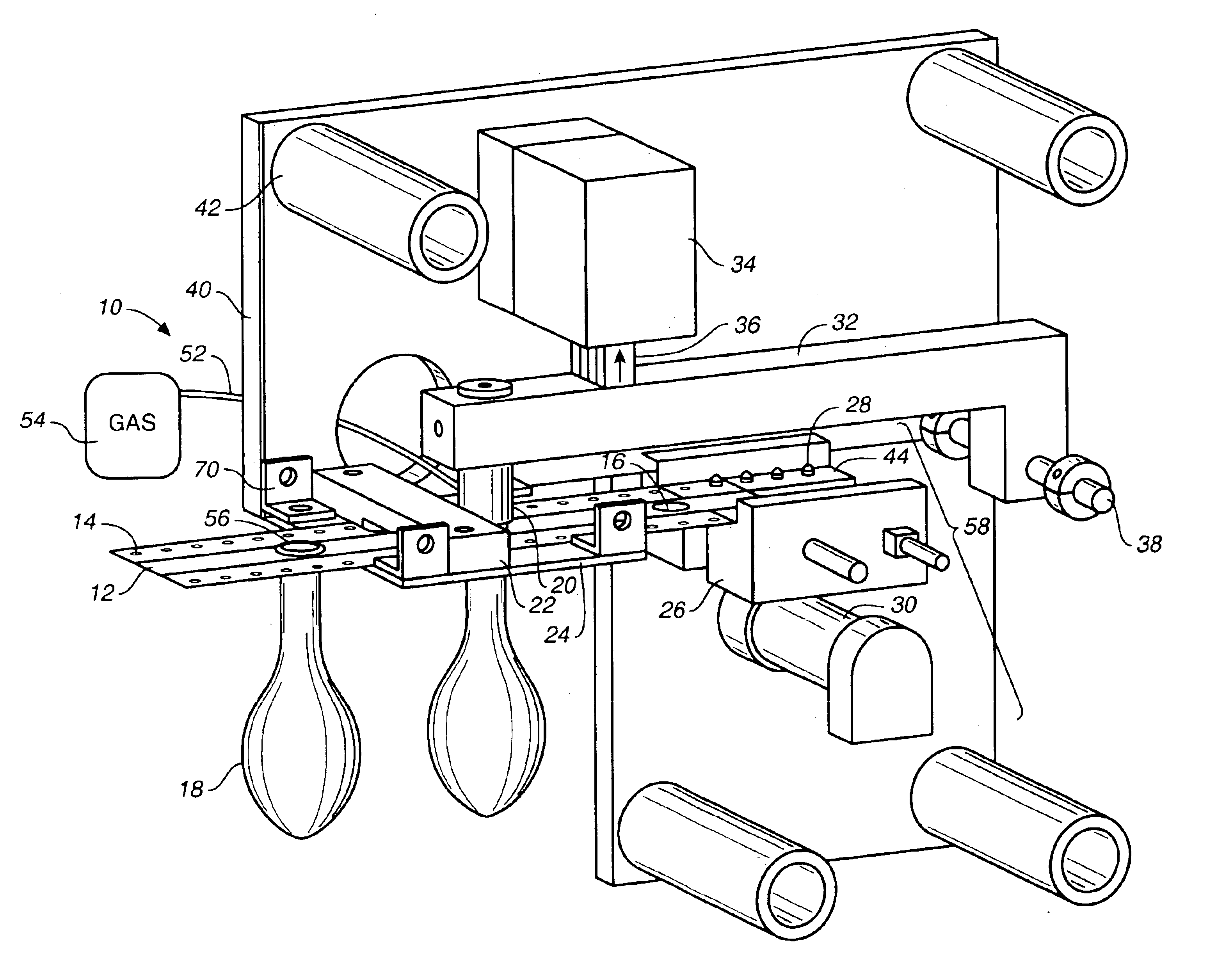
[0008]The objects are met by a system and method for filling balloons that employ a digital motion control apparatus moving a removable media with attached balloons that may be assembled away from the actual machine that will inflate the balloons. Uninflated balloons are attached by the neck to a reusable web, which has evenly-space openings down the center of the web for attaching balloons. Balloons may be attached to the web at any time before the balloons are to be filled. The web also has a set of perforations along each side of the length of the web. These perforations are for attaching the web to pins on the balloon-inflating machine's tractor drive. The machine's tractor drive with a digitally-controlled stepper motor ensures that the pins powered by the tractor drive move a precise distance at each cycle. Since the pins move a precise distance, the web with attached balloons is advanced accurately to the filling nozzle each time the web is incrementally advanced. The filling nozzle, attached to a canister of compressed gas, is placed in the neck of the balloon to fill the balloon. After the balloon is inflated, the filling nozzle is removed. The balloon can either be manually detached and tied off by the user or the neck of the balloon may contain a clip assembly that both prevents escape of gas from the balloon and detaches it from the machine.

Problems solved by technology

These can be quite time-consuming tasks.
Additionally, balloons may be damaged or filled to different volumes.
Due to the drawbacks of these methods, machines are often used to fill balloons.
This is potentially time-consuming and costly.
All of the prior art described above requires complex machinery with many moving parts.

Method used


Image

  • System and method for inflating balloons
  • System and method for inflating balloons
  • System and method for inflating balloons

Examples


Embodiment Construction

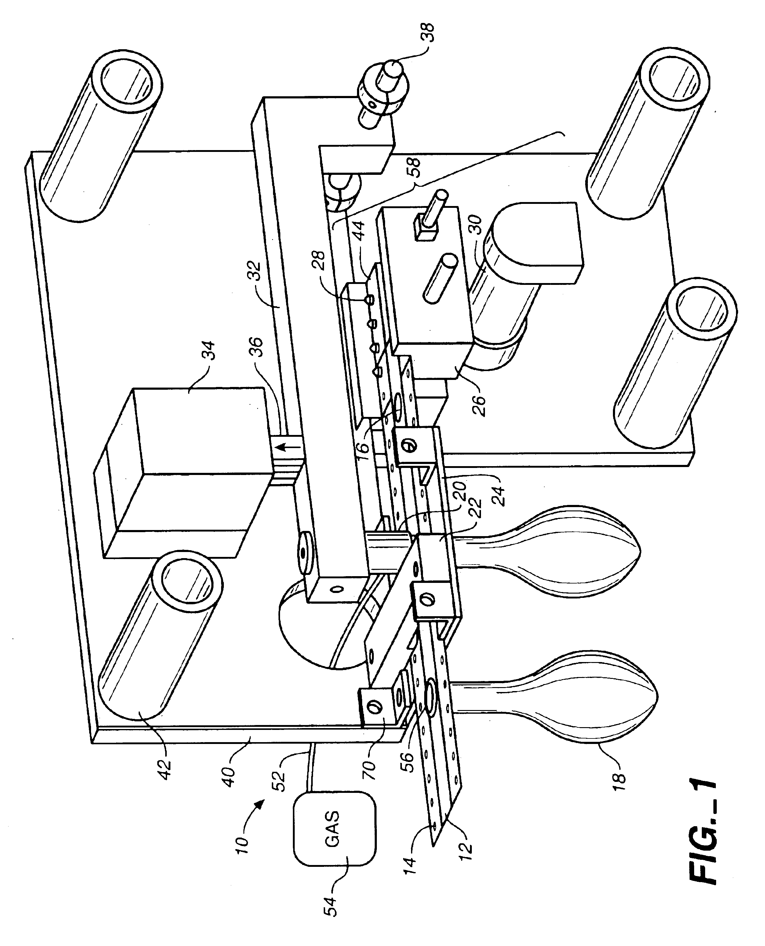
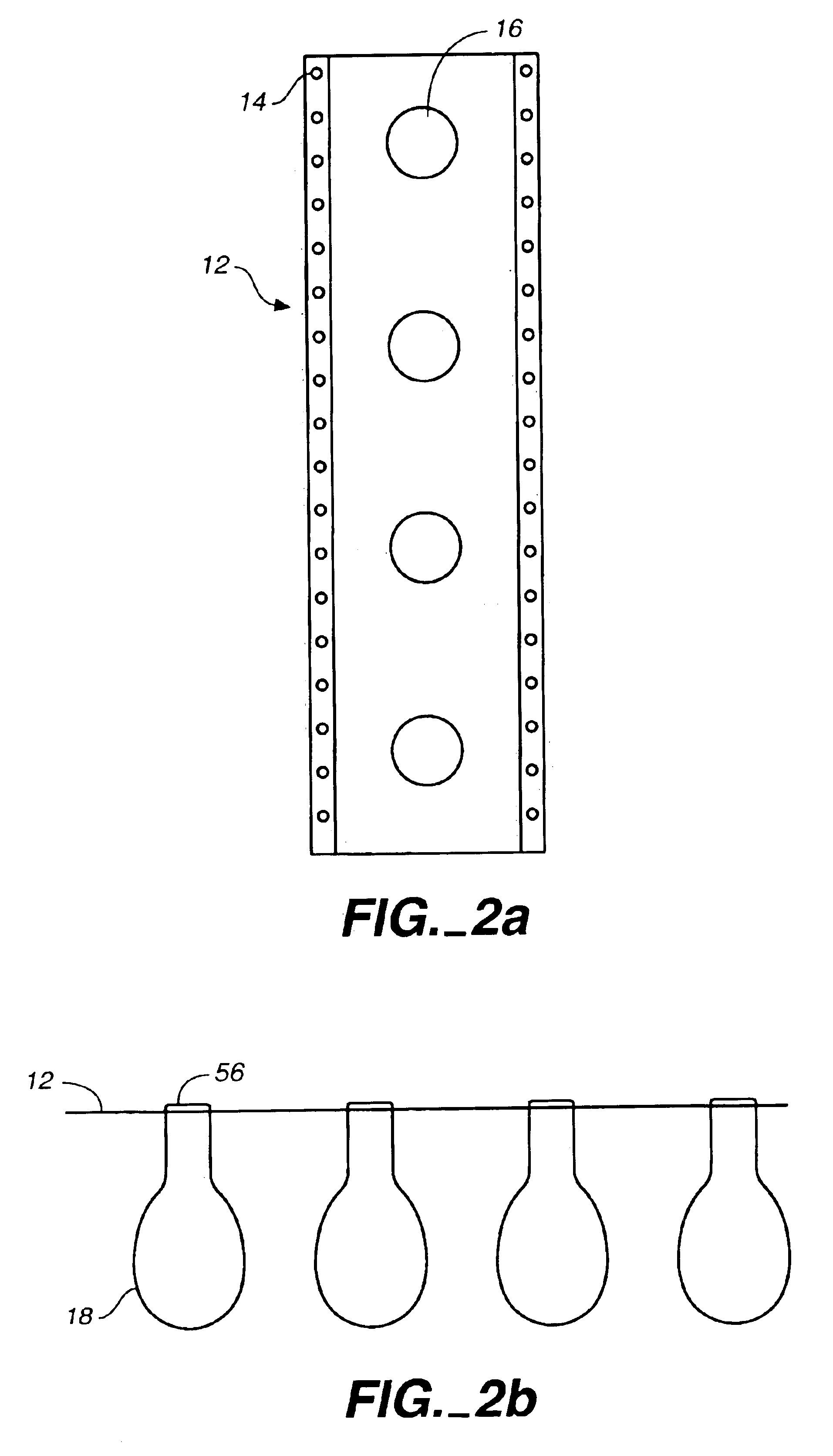
[0014]With respect to FIG. 1, balloon filling machine 10 is shown supporting web 12 (see FIGS. 2a and 2b, below) containing uninflated balloons 18 attached by the neck 56 in evenly-spaced holes 16. Web 12 is loaded onto pins 28 of a tractor drive 58, using tractor feed sprockets similar to such mechanisms in many dot matrix printers. The web 12 is attached to pins 28 of the tractor drive 58 by means of evenly-spaced perforations, or holes, 14 running down each side of the web 12.

[0015]A portion of the web 12 is shown in FIG. 2a. It is made of fabric, paper, or a synthetic material. Evenly-spaced holes 16 are located in the center portion of the web 12. These holes 16 are sized so as to hold the neck of an uninflated balloon in place. A set of evenly-spaced perforations 12 runs down either side of the web 12. This set of perforations 12 is sized so as to fit on the pins of the machine's tractor drive. A specific dye cut may be used to produce a web with appropriately-sized holes 12, ...


PUM

PropertyMeasurementUnit
distanceaaaaaaaaaa
lengthaaaaaaaaaa
tensionaaaaaaaaaa

Abstract

A system and method for filling balloons. A reusable web holding uninflated balloons attached at the neck is loaded onto a machine for inflating balloons. This machine features a digital motion control apparatus which advances the web a precise distance. After the web advances, a supply nozzle is inserted into the neck of the uninflated balloon directly beneath the nozzle. The balloon is filled, the supply nozzle lifted, and the balloon is removed from the machine. The web is then advanced again and another balloon is filled.

Description

FIELD OF THE INVENTION[0001]This invention relates to machines for inflating balloons.BACKGROUND ART[0002]Balloons are ubiquitous at a wide variety of events including political conventions, dances, children's birthday parties, fairs, and sales at car dealerships. Balloon displays often require large numbers of balloons, each of which has to be filled. Various methods may be employed to fill balloons. An individual may blow up and tie each balloon by hand or use a tank of compressed air or helium to inflate the balloon, which then has to be tied. These can be quite time-consuming tasks. Additionally, balloons may be damaged or filled to different volumes. Due to the drawbacks of these methods, machines are often used to fill balloons.[0003]The prior art contains several machines for filling balloons. U.S. Pat. No. 3,380,490 discloses a balloon vending machine having balloons fixed by their necks in a flexible loop which is advanced at a turning point. As the loop advances, an uninfl...

Claims


Application Information

Patent Timeline
Patent Type & Authority Patents(United States)
IPC IPC(8): A63H27/10A63H27/00
CPCA63H27/10A63H2027/1033
Inventor RATERMANN, GEORGE W.
Owner RATERMANN GEORGE W
Learn More