Method and apparatus for fabricating variable gauge, contoured composite stiffeners

a composite stiffener and variable gauge technology, applied in the field of composite structure fabrication, can solve the problems of increased manufacturing flow time, difficulty, labor intensiveness, etc., and achieve the effects of reducing ply wrinkling, reducing tooling costs and process flow time, and reducing ply misalignmen

Active Publication Date: 2013-06-18
THE BOEING CO
View PDF87 Cites 46 Cited by
  • Summary
  • Abstract
  • Description
  • Claims
  • Application Information

AI Technical Summary

Benefits of technology

[0008]The disclosed embodiments provide a method and apparatus for fabricating blade type stringers using simplified tooling to form a single composite charge into a desired stringer configuration. Tooling costs and process flow times may be reduced by eliminating the need to form multiple charges and assemble multiple stiffener members in order to achieve the desired stringer configuration. The embodiments allow localized contouring of the stringer by accommodating ply pad-ups and ply drop-offs along the length of the stringer. The charge may be contoured along its length during forming with reduced ply wrinkling and / or reduced ply misalignment.

Problems solved by technology

Fabricating blade stringers using multiple separate charges requires multiple tools, is relatively labor intensive and may add to manufacturing flow times.
Difficulty may be encountered, however, when attempting to form highly contoured stringers using conventional tooling because of the tendency of the plies in the charge to wrinkle as the charge is being compressed.
Accordingly, fabrication of highly contoured stringers using composites is generally limited to hand layup techniques in which each ply is laid up by hand over a die or other tool in order to reduce the possibility of ply wrinkling.
The hand layup technique is labor intensive, and thus costly as well as relatively slow.

Method used


Image

  • Method and apparatus for fabricating variable gauge, contoured composite stiffeners
  • Method and apparatus for fabricating variable gauge, contoured composite stiffeners
  • Method and apparatus for fabricating variable gauge, contoured composite stiffeners

Examples


Embodiment Construction

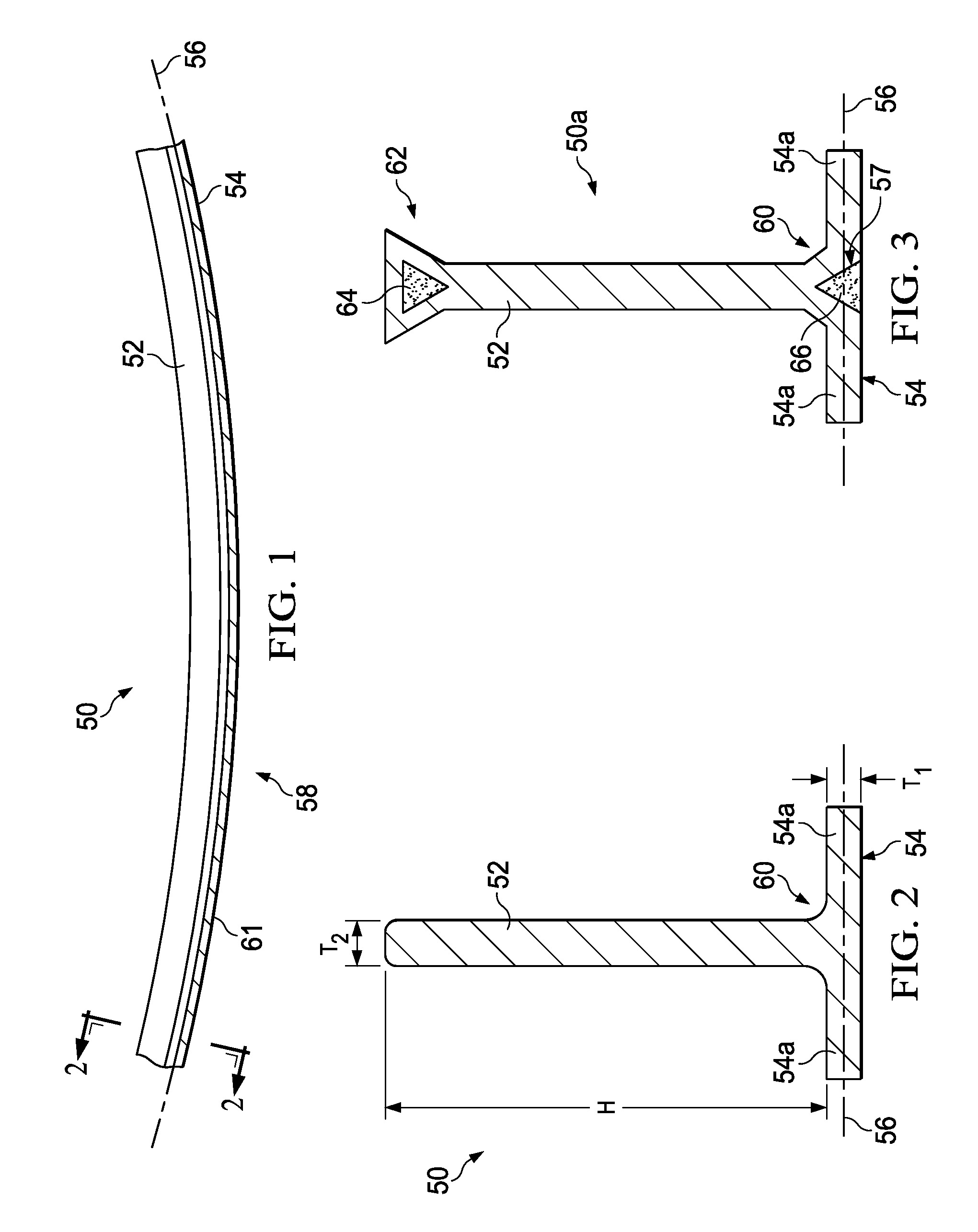
[0028]Referring first to FIGS. 1 and 2, the disclosed embodiments relate to a method and apparatus for fabricating an elongate, composite stiffener, such as a blade type stringer 50 having a substantially flat blade 52 and a flange 54 extending substantially perpendicular to the blade 52. The flange 54 includes a pair of flange portions 54a laterally extending from one end of the blade 52, and connected to the blade 52 by a radius section 60. The blade stringer 50 may have one or more contours 58 along its length. In the illustrated embodiment, the stringer 50 has a substantially constant contour 58 in the curved plane 56 of a flange 54. In other embodiments, the stringer 50 may have one or more of the contours 58 which may or may not be of constant curvature. Also, as will be discussed later in more detail, the flange 54 may have a variable gauge or thickness T1 at one or more locations along its length in order to conform the stringer 54 to localized contours of a structure to whi...


PUM

PropertyMeasurementUnit
shapeaaaaaaaaaa
temperatureaaaaaaaaaa
lengthaaaaaaaaaa

Abstract

Tooling apparatus for forming a composite charge into a contoured composite blade stringer includes an elongate punch and an elongate die flexible along their lengths. The charge is press formed by using the punch to drive the charge into the die. The punch and the die are mounted between a pair of flexible plates. A press coupled with the plates contours the charge by bending the plates into a desired contour.

Description

CROSS REFERENCE TO RELATED APPLICATIONS[0001]This application is related to co-pending U.S. patent application Ser. No. 12 / 258,404 filed Oct. 25, 2008, and Ser. No. 12 / 128,173 fled May 28, 2008, which are incorporated by reference herein in their entireties.BACKGROUND INFORMATION[0002]1. Field[0003]This disclosure generally relates to the fabrication of composite structures, and deals more particularly with a method and apparatus for forming flat composite charges into contoured, reinforcing substructures, such as variable gauge blade stiffeners.[0004]2. Background[0005]Composite reinforcing substructures such as blade stiffeners, sometimes referred to as blade stringers, are frequently used in the marine and aircraft industries. These stringers may be fabricated by combining two or more stiffening members. For example, blade-type stringers can be fabricated by combining two members having L or C cross sectional shapes, back-to-back. These members may be formed by manually hot drape...

Claims


Application Information

Patent Timeline
Patent Type & Authority Patents(United States)
IPC IPC(8): B29C51/14
CPCB29C70/462B29L2031/001Y10T156/1002Y10T156/1028Y10T156/1008Y02T50/433B29C70/461Y02T50/40B21D47/00
Inventor ROTTER, DANIEL M.CHAPMAN, MICHAEL R.COXON, BRAD A.NELSON, PAUL E.
Owner THE BOEING CO
Why Eureka
Try Eureka