Heat dissipating device of an electromotor

a technology of heat dissipation device and electromotor, which is applied in the direction of mechanical energy handling, dynamo-electric machines, supports/encloses/casings, etc., can solve the problems of increasing cost, increasing heat dissipation burden, and affecting the efficiency of electromotors, so as to shorten the heat cycle and effectively rota

Active Publication Date: 2013-06-18
METAL INDS RES & DEV CENT
View PDF5 Cites 1 Cited by
  • Summary
  • Abstract
  • Description
  • Claims
  • Application Information

AI Technical Summary

Benefits of technology

[0010]The invention is characterized in that: the outer blade of the roller can be effectively rotated by the wind force without requiring additional power. In the invention, a rotation action is employed. An inner blade is used to continuously take the liquid contacting the heat source away from the heat source, and bring the liquid at lower temperature to contact the heat source, thereby shortening the heat cycle. Moreover, by using the rotation action, the contact position between the outer blade and the fresh wind is continuously changed to enable each outer blade to continuously contact the fresh wind so as to obtain a desired cooling effect.

Problems solved by technology

However, this heat dissipation technology largely relies on conditions such as the ambient temperature, ventilation performance, and ventilation rate of the heat ambient fins.
If the conditions are undesirable, the heat dissipation efficacy is not obvious, and the high heat generated by the electromotor still remains on the surface of the heat dissipating fins, wherein the high heat may cause damages to the electromotor due to overheating.
However, for this case, in addition to extra power consumption or load, the heat dissipating fan itself also generates heat and causes heat dissipation burden.
However, this technology needs to further provide a set of actuating pumping apparatus and heat dissipating device, so that the cost is increased and more power is consumed.
Besides, the electric pump itself also generates heat to cause heat dissipating burden, and occupies a space in the equipment due to the pumping apparatus and the heat dissipating device located thereon.

Method used


Image

  • Heat dissipating device of an electromotor
  • Heat dissipating device of an electromotor
  • Heat dissipating device of an electromotor

Examples


Embodiment Construction

[0016]Preferred embodiments of the invention are illustrated in detail below with the accompanying drawings.

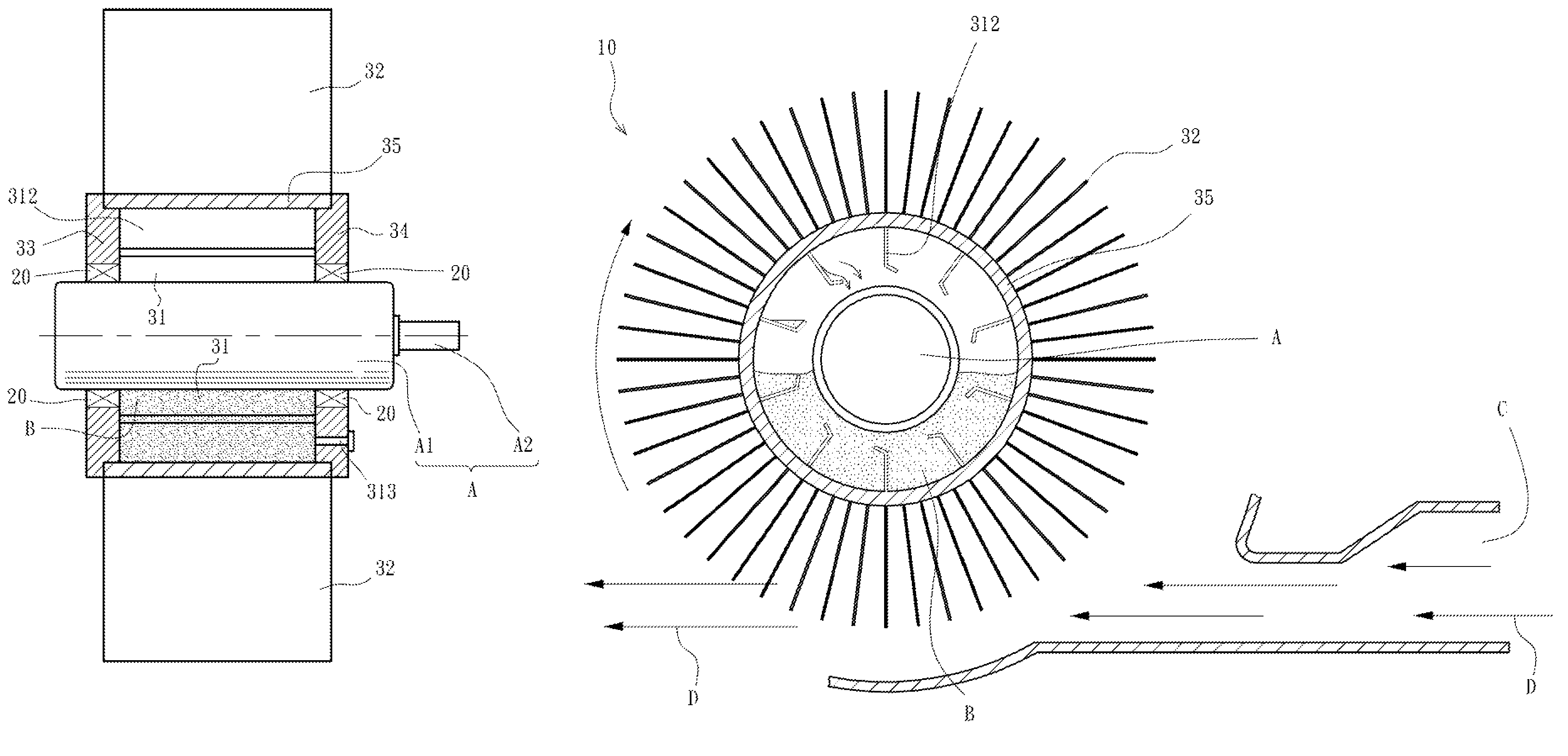
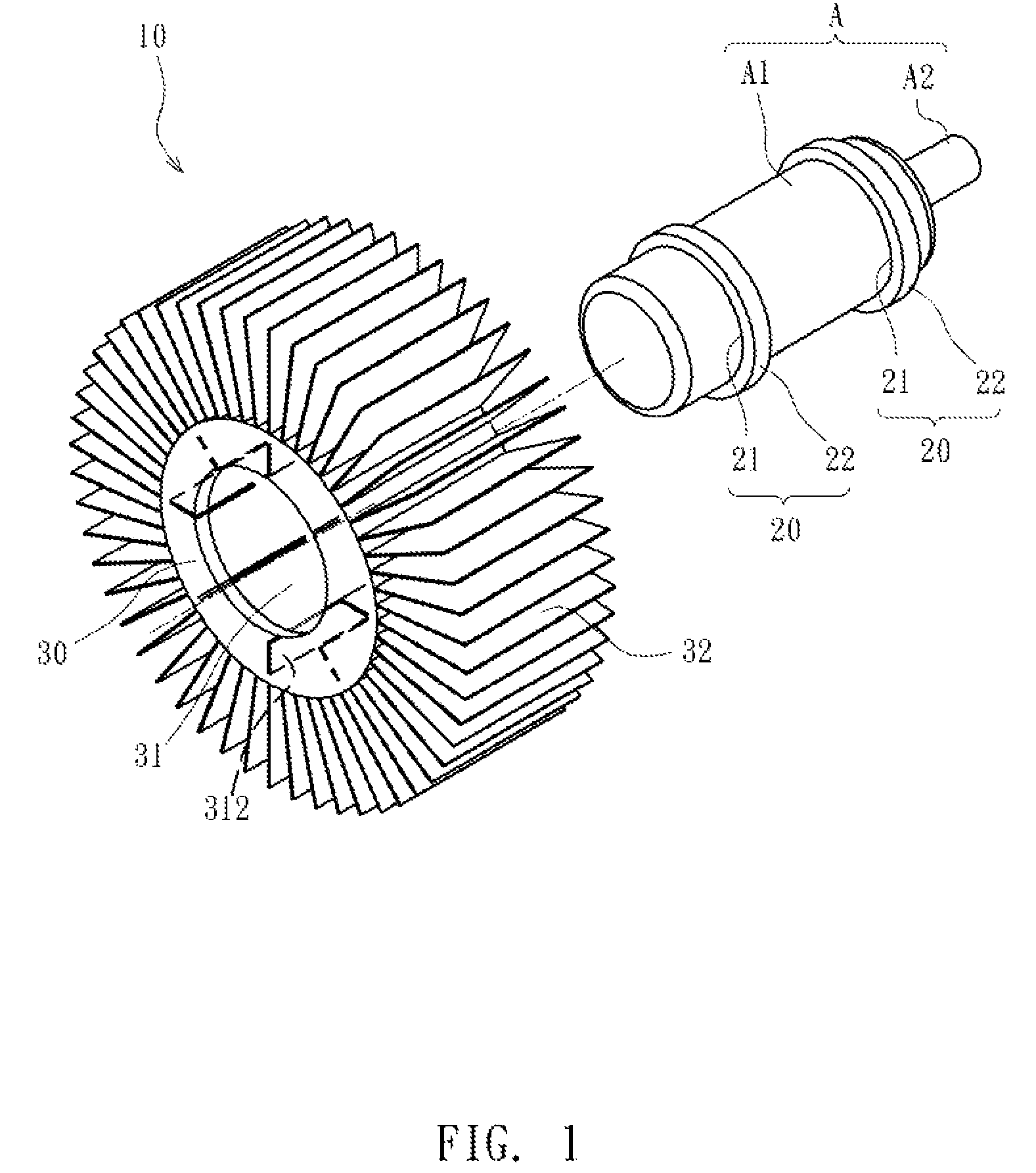
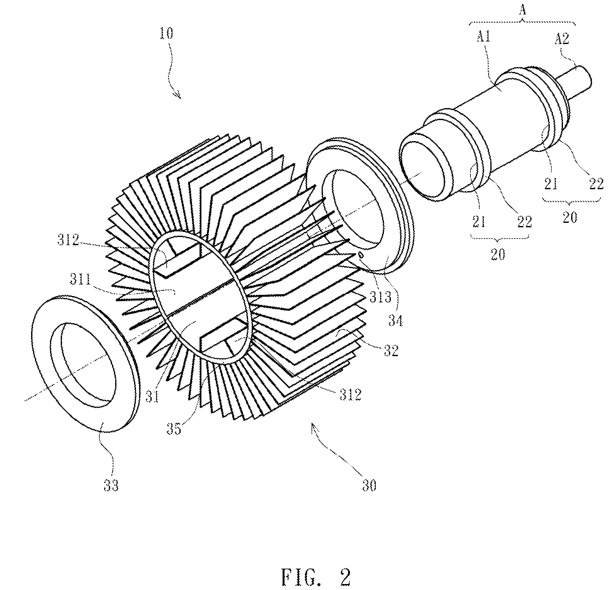
[0017]FIG. 1 is a three-dimensional exploded view of a heat dissipating device of an electromotor, wherein the heat dissipating device has a roller integrally formed thereon according to an embodiment of the invention. The heat dissipating device 10 in this embodiment is applied to an electromotor A having a casing A1 and a driving shaft A2. The heat dissipating device 10 includes a pair of bearings 20, each having an inner sleeve 21 and an outer annular seat 22. The inner sleeves 21 are hermetically disposed around the casing A1 of the electromotor A, and the inner sleeves 21 and the casing A1 are sealed to achieve a sealing state between the casing A1 and the bearings 20. Further, a roller 30 is hermetically disposed around the outer annular seats 22 of the pair of bearings 20. A sealed chamber 31 is formed in the roller 30, and the chamber 31 covers a surface of the casing ...


PUM


Abstract

A heat dissipating device of an electromotor is a composite cooling device driven in a powerless manner and used for stirring a cooling liquid applied on a surface of a casing of the electromotor. The heat dissipating device includes a pair of bearings fitted on the casing, and a roller disposed at outer ring seats of the pair of bearings. The roller has a sealed chamber therein, the chamber covers a surface of the casing located in a disposition region of the bearings, and at least one outer blade is disposed outside the roller. Thereby, composite heat dissipating of liquid cooling and air cooling of the electromotor is implemented with a cooling liquid injected into the chamber of the roller and a wind force applied on the outer blade.

Description

CROSS-REFERENCE TO RELATED APPLICATION[0001]This application claims the benefit of Taiwan Patent Application No. 098133145, filed on Sep. 30, 2009, which is hereby incorporated by reference for all purposes as if fully set forth herein.BACKGROUND OF THE INVENTION[0002]1. Field of Invention[0003]The invention relates to a heat dissipating device of an electromotor, and more particularly to a composite heat dissipating device with interactive actions of liquid cooling and air cooling of an electromotor.[0004]2. Related Art[0005]As a conventional electromotor generates high heat during operation, a heat dissipating device needs to be disposed on a machine body to reduce the operating temperature, and the commonly used heat dissipating devices are generally an air cooling type or a liquid cooling type heat dissipating devices.[0006]The air-cooling type electromotor is the most popular. Heat dissipating fins are usually disposed on the casing of the electromotor, to improve heat dissipat...

Claims


Application Information

Patent Timeline
Patent Type & Authority Patents(United States)
IPC IPC(8): H02K9/00
CPCH02K9/14H02K9/22H02K9/19H02K9/227
Inventor HUANG, CHIN-CHUAN
Owner METAL INDS RES & DEV CENT
Why Eureka
Try Eureka