Thermochemical nanolithography components, systems, and methods

a technology of nanolithography and components, applied in the field of nanolithography, can solve the problems of increasing the cost of lithographic materials, etc., and achieves the effect of chemical patterning, patterning speed, and topographical change control

Active Publication Date: 2013-06-18
GEORGIA TECH RES CORP
View PDF11 Cites 9 Cited by
  • Summary
  • Abstract
  • Description
  • Claims
  • Application Information

AI Technical Summary

Problems solved by technology

Many currently existing lithographic techniques, however, have significant limitations in terms of resolution, writing speed, and the chemical diversity of the materials that can be patterned on a particular substrate.
By way of example, dip-pen nanolithography (DPN) offers several interesting capabilities, but requires stringent control over the environment / atmosphere and has limitations in substrate choice, patterning speed, and topographical change control.
In contrast, achieving chemical patterning, even at resolutions of less than or equal to about 100 nm, still remains a challenge because of the difficulty in spatially confining chemical reactions and because of the need to control the interactions of the reactant and products with the substrates and, if necessary, stamps.
By extension, combining the two concepts (i.e., topographical and chemical nanopatterning) has been even more challenging.
While advances have been made in patterning inorganic nanoscale objects, challenges still exist, in particular, for protein and DNA nanolithography.
Many protein nanopatterning techniques are unable to produce features below 100 nm, and even fewer can attain resolutions on the order of about 50 nm.
In addition, only a few protein nanopatterning techniques have been established for independently patterning multiple protein species on the same surface.
Still further, bioactivity is a particularly delicate problem because denaturation, oxidation, and dehydration in air are common drawbacks that complicate many potential protein nanopatterning techniques.
These considerations also limit the choice of surfaces onto which the proteins can be patterned.

Method used


Image

  • Thermochemical nanolithography components, systems, and methods
  • Thermochemical nanolithography components, systems, and methods
  • Thermochemical nanolithography components, systems, and methods

Examples


example 1

Synthesis of Poly((tetrahydropyran-2-yl N-(2-methacryloxyethyl)carbamate)-co-(methyl 4-(3-methacryloyloxypropoxy)cinnamate)) Polymer

[0108]In this example; a new polymeric material, poly((tetrahydropyran-2-yl N-(2-methacryloxyethyl)carbamate)-co-(methyl 4-(3-methacryloyloxypropoxy)cinnamate)) was synthesized. This polymer had both a deprotecting group and a cross-linking group. The deprotecting group was the THP carbamate functionality, and the cross-linking group was the cinnamate functionality. The polymer has the following structure:

[0109]

[0110]The polymer in this example was prepared using the following chemicals for the synthesis: dihydropyran (Aldrich), 2-isocyanatoethyl methacrylate (Aldrich), azobisisobutyronitrile (Aldrich), allyl bromide (Aldrich), potassium carbonate (VWR), platinum on activated carbon (10 wt %, Strem Chemicals), 4-hydroxybenzophenone (Alfa Aesar), and chlorodimethyl silane (Alfa Aesar). All solvents were reagent grade. All chemicals were used as-received ...

example 2

TCNL of Multifunctional Templates for Assembling Nanoscale Objects

[0125]In this example, TCNL was used to thermally activate the deprotection of amine groups on a polymer surface in arbitrary nanoscale and microscale patterns at linear speeds of up to millimeters per second. The unmasked amine nanotemplates were then selectively and covalently functionalized to create patterns of thiols, maleimides, aldehydes or biotins in distinct areas of the polymer surface. The multiple functionalities of these patterns were exploited to create nanoarrays, with features as small as about 40 nm, of nanoscale objects such as bioactive proteins and DNA. By repeating the TCNL steps followed by different protocols for chemically converting the unprotected amines, it was possible to generate surfaces with orthogonal functionalities in distinct areas that were further functionalized at a later date. The bioactivity of the TCNL-designed protein arrays was confirmed by using fluorescent antibodies and a ...

example 3

Direct TCNL Patterning and Characterization of Poly(p-Phenylene Vinylene) Nanostructures

[0144]In this example, TCNL was used to prepare poly(p-phenylene vinylene) (PPV), which is a widely studied electroluminescent conjugated polymer. Direct writing of PPV by locally heating a sulfonium salt precursor was achieved with sub-100 nm spatial resolution in ambient conditions. The local thermochemical conversion was verified by Raman spectroscopy, fluorescence imaging, and atomic force microscopy. This convenient direct writing of conjugated polymer nanostructures could be desirable for the design and fabrication of future nanoelectronic, nanophotonic, and biosensing devices.

[0145]A solution of a sulfonium salt precursor, poly(p-xylene tetrahydrothiophenium chloride) (0.25 wt % in H2O, Aldrich), was drop cast on either glass slides or Si (111) wafers that had been immersed overnight in a piranha solution. The thermal conversion to PPV typically involves the elimination of both thiophene a...


PUM

PropertyMeasurementUnit
speedaaaaaaaaaa
moving speedaaaaaaaaaa
distanceaaaaaaaaaa

Abstract

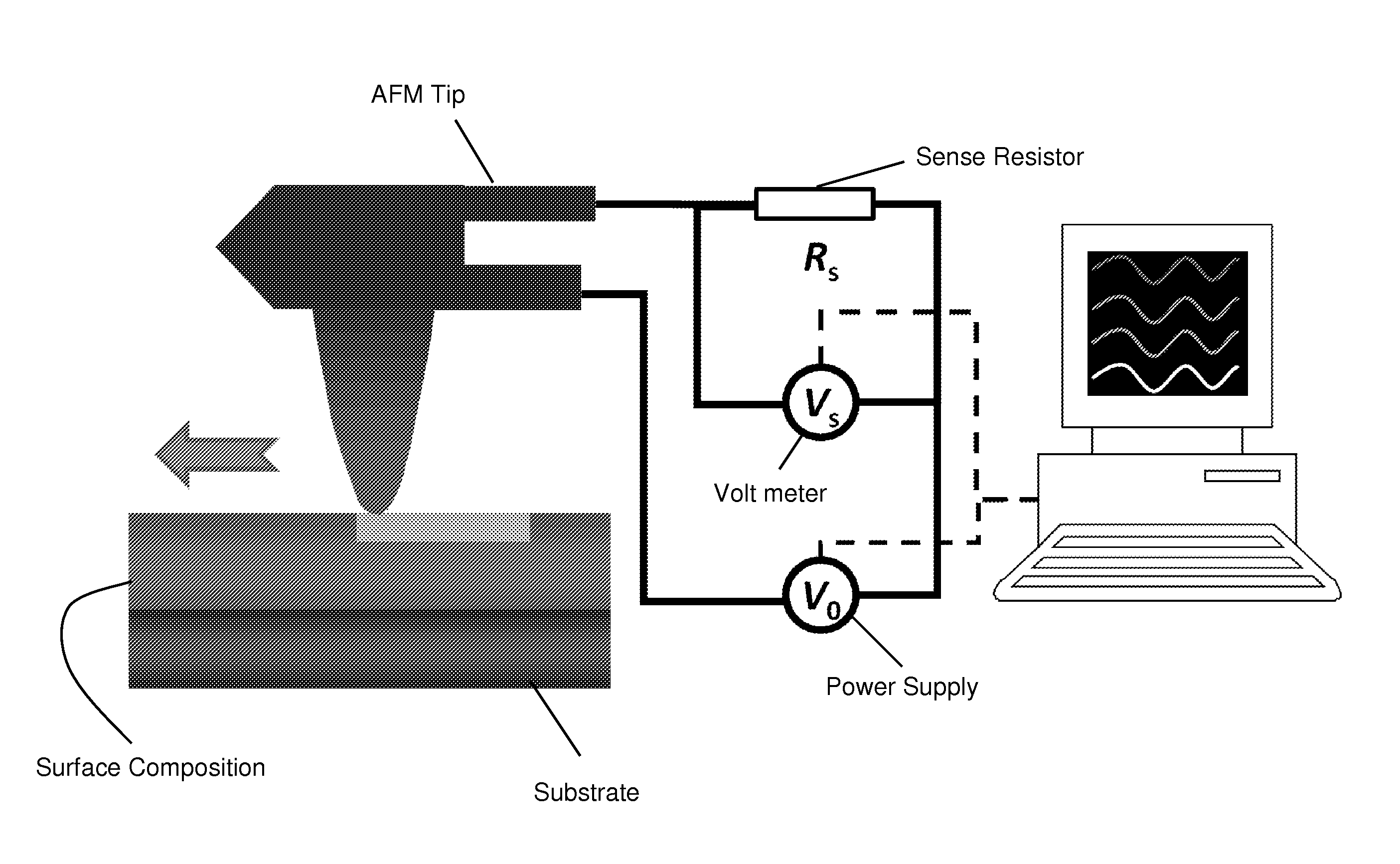
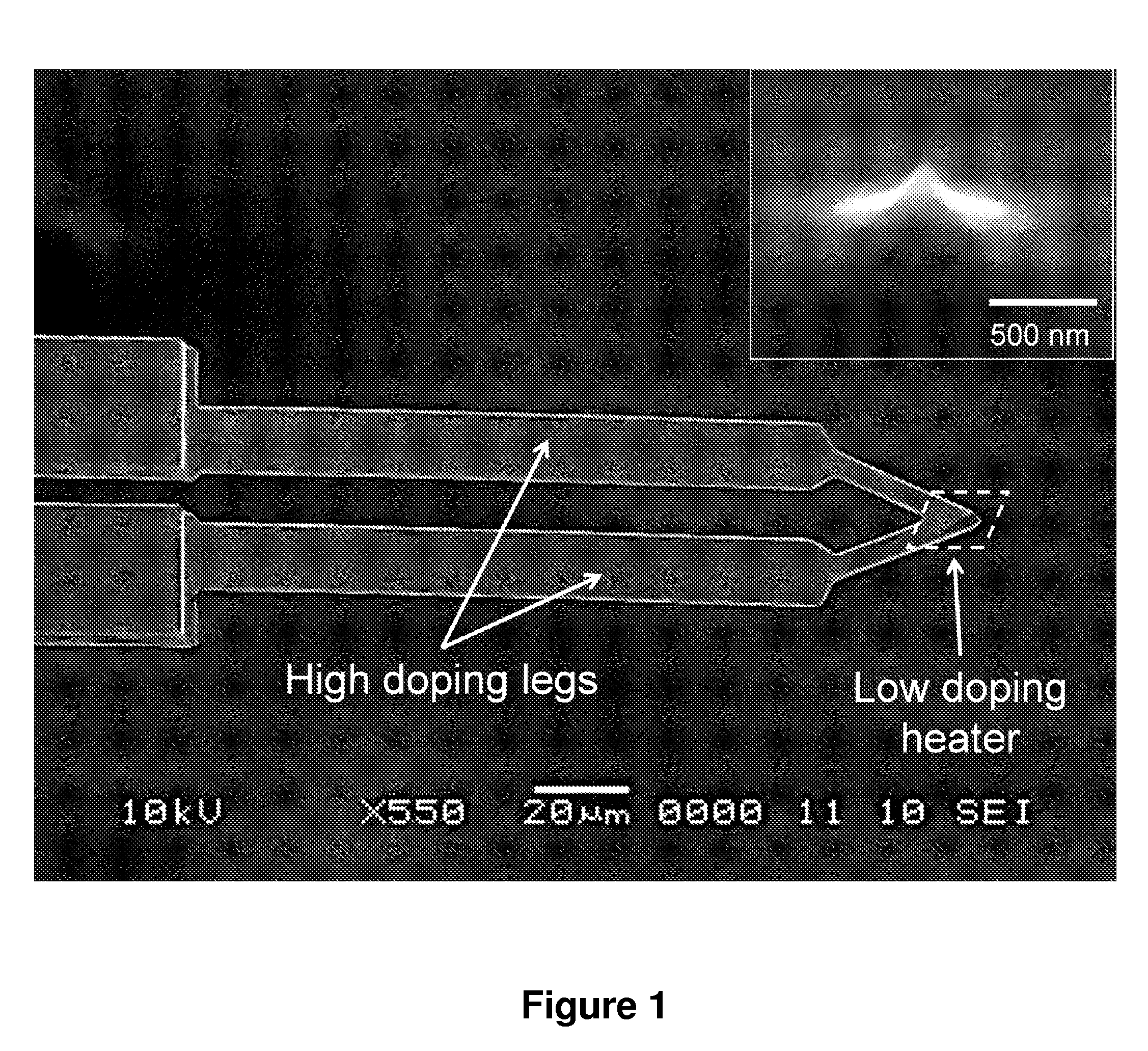
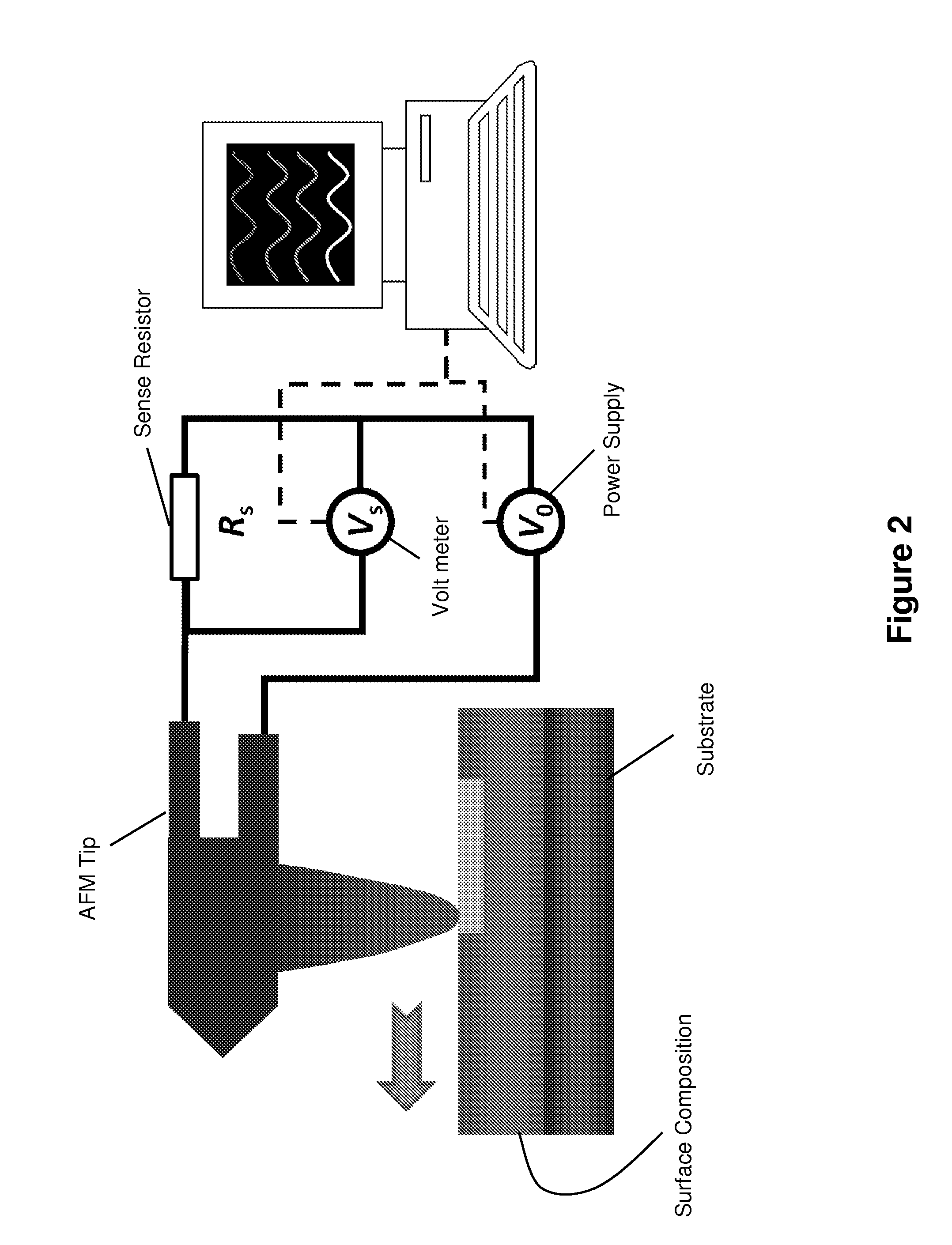
Improved nanolithography components, systems, and methods are described herein. The systems and methods generally employ a resistively heated atomic force microscope tip to thermally induce a chemical change in a surface. In addition, certain polymeric compositions are also disclosed.

Description

CROSS-REFERENCE TO RELATED APPLICATION[0001]The present application claims the benefit of U.S. Provisional Patent Application Ser. No. 61 / 182,190, filed 29 May 2009, and entitled “Thermochemical Nanolithography of Multi-Functional Materials,” which is hereby incorporated by reference in its entirety as if fully set forth below.STATEMENT OF FEDERALLY SPONSORED RESEARCH[0002]This invention was made with United States Government support under Grant Nos. DMR-0120967, DMR-0820382, and DMR-0706031 all awarded by the National Science Foundation and Grant No. DE-FG02-06ER46293 awarded by the Department of Energy. The United States Government has certain rights in this invention.TECHNICAL FIELD[0003]The various embodiments of the present invention relate generally to nanolithography. More particularly, the various embodiments of the present invention relate to systems and methods for implementing chemical nanolithography techniques, the components used to implement such techniques, and the p...

Claims


Application Information

Patent Timeline
Patent Type & Authority Patents(United States)
IPC IPC(8): G01Q60/24G01Q60/38
CPCB82Y10/00B82Y40/00G03F7/0002G03F7/2049G01Q80/00G03C5/00G03F7/00
Inventor RIEDO, ELISAMARDER, SETH R.DE HEER, WALT A.SZOSKIEWICZ, ROBERT J.KODALI, VAMSI K.JONES, SIMON C.OKADA, TAKASHIWANG, DEBINCURTIS, JENNIFER E.HENDERSON, CLIFFORD L.HUA, YUEMING
Owner GEORGIA TECH RES CORP
Why Eureka
Try Eureka