Method and device for generating three-dimensional array hollow light spot
What is AI technical title?
AI technical title is built by PatSnap AI team. It summarizes the technical point description of the patent document.
A technology of three-dimensional array and generation method, applied in optics, optical components, instruments, etc., can solve the problems of non-adjustable spot position and non-hollow spot intensity distribution
Inactive Publication Date: 2017-07-07
LUDONG UNIVERSITY
View PDF7 Cites 19 Cited by
Summary
Abstract
Description
Claims
Application Information
AI Technical Summary
This helps you quickly interpret patents by identifying the three key elements:
Problems solved by technology
Method used
Benefits of technology
Problems solved by technology
Chinese invention patent [CN201410360641.8] discloses a method for generating array spot, but only produces two-dimensional square array spot, not three-dimensional array spot, and the position of the spot is not adjustable, and the intensity distribution of the spot is not hollow
Method used
Image
Click on the blue label to locate the original text in one second.
Reading with bidirectional positioning of images and text.
Examples
Embodiment 1
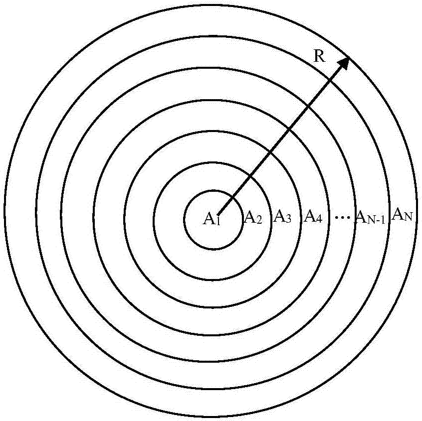
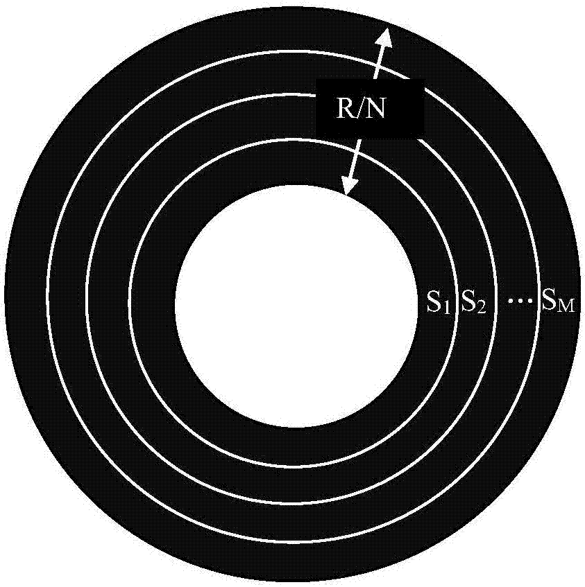
[0103] Select the number of rings N=80, the number of sub-rings M=8, corresponding to M=8, it is a three-dimensional square array, and the position parameter of each light spot is (Δx 1 ,Δy 1 ,Δz 1 )=[2μm, 2μm, 2μm]; (Δx 2 ,Δy 2 ,Δz 2 )=[-2μm, 2μm, 2μm]; (Δx 3 ,Δy 3 ,Δz 3 ) = [-2μm, -2μm, 2μm]; (Δx 4 ,Δy 4 ,Δz 4 )=[2μm,-2μm,2μm]; (Δx 5 ,Δy 5 ,Δz 5 )=[2μm, 2μm, 0μm]; (Δx 6 ,Δy 6 ,Δz 6 )=[-2μm, 2μm, 0μm]; (Δx 7 ,Δy 7 ,Δz 7 )=[-2μm,-2μm,0μm]; (Δx 8 ,Δy 8 ,Δz 8 )=[2 μm, −2 μm, 0 μm].
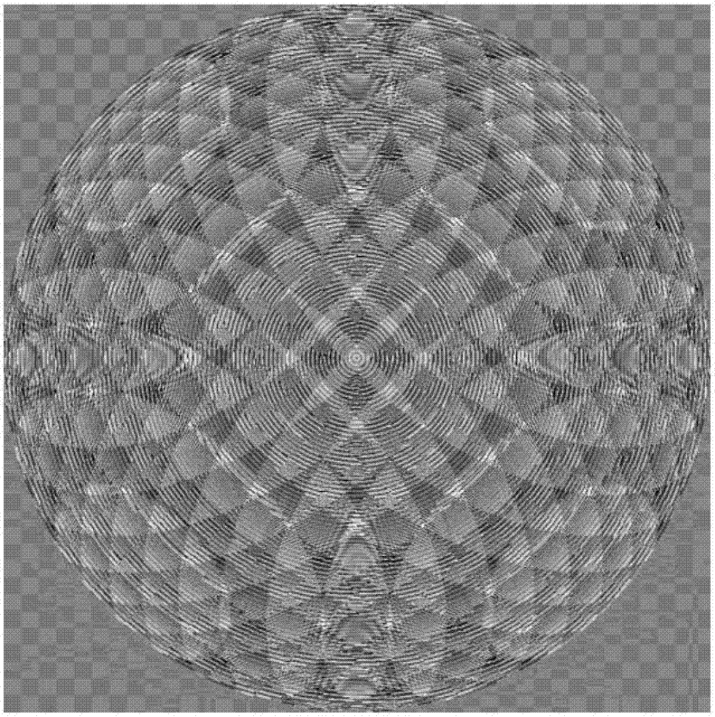
[0104] Figure 4 Shown is a schematic diagram of the device for generating a three-dimensional array of spots. A device for generating a three-dimensional array hollow spot, such as Figure 4 As shown, it includes a laser 1 , a pinhole filter 2 , a collimating lens 3 , a half-wave plate 4 , a spatial light modulator 5 , a light-wave converter 6 , a beam diameter changer 7 and an objective lens 8 . The spatial light modulator 5 is loaded with image 3 Phase shown Figure 10...
Embodiment 2
[0111] The phase diagram when M=9 array spots is selected, such as Figure 11 As shown, where the number of rings N=60, corresponding to the position parameters of 9 spots: (Δx 1 ,Δy 1 ,Δz 1 )=[2cos(π / 4)μm, 2sin(π / 4)μm,1μm], (Δx 2 ,Δy 2 ,Δz 2 )=[2cos(π / 2)μm, 2sin(π / 2)μm,1μm], (Δx 3 ,Δy 3 ,Δz 3 )=[2cos(3π / 4)μm, 2sin(3π / 4)μm,1μm], (Δx 4 ,Δy 4 ,Δz 4 )=[2cos(π)μm, 2sin(π)μm,1μm], (Δx 5 ,Δy 5 ,Δz 5 )=[2cos(5π / 4)μm, 2sin(5π / 4)μm,1μm], (Δx 6 ,Δy 6 ,Δz 6 )=[2cos(3π / 2)μm, 2sin(3π / 2)μm,1μm], (Δx 7 ,Δy 7 ,Δz 7 )=[2cos(7π / 4)μm, 2sin(7π / 4)μm,1μm], (Δx 8 ,Δy 8 ,Δz 8 )=[2cos(2π)μm, 2sin(2π)μm,1μm], (Δx 9 ,Δy 9 ,Δz 9 )=[0 μm, 0 μm, −1 μm].
[0112] Figure 12 It shows that when the parameter M=9 is selected and the light-wave converter composed of a helicalphase plate and a quarter-wave plate is selected, the light wave is loaded with a phase of topological charge n=1 and the polarization becomes a three-dimensional equation of left-handed circularly polarized light...
PUM
Abstract
The invention relates to a method and device for generating a three-dimensional array hollow light spot. The device comprises a laser device, a pinhole filter, a collimator lens, a half-wave plate, a spatial light modulator, an optical wave converter, a beam diameter changer and a microobjective. In addition, the method includes: laser emitted by the laser device is converted into a linear polarization type plane wave; wave-front phase modulation is carried out on the linear polarization type plane wave; and then light after wave-front phase modulation is focused by an objective lens to generate an array light spot. The wave-front phases are in three-dimensional spatial position controllable array light spot phase distribution; and the light wave after wave-front phase modulation needs to be processed by modulation of circular polarization with a spiral phase or angular polarization without a spiral phase. The array light spot is formed by a plurality of hollow light spots arranged in three-dimensional space and each light spot can move precisely in the three-dimensional space. The method and device can be applied to array optical tweezers, super-resolution microscopic imaging and super-resolution nanometer lithography fields.
Description
technical field [0001] The invention relates to a method and device for generating an array spot, in particular to an array spot with a three-dimensional array structure, each spot position is adjustable, and the spot is a hollow structure, which can be used for array optical tweezers, super-resolution microscopic imaging In the field of super-resolution nanolithography. Background technique [0002] The so-called hollow spot means that the center of the spot after the beam is focused is a dark nucleus, where the light intensity is zero. Hollow spots are needed in the fields of optical tweezers technology, high-resolution imaging, and high-density optical storage. "high refractive index" microparticles, and can also capture "low refractive index" microparticles or living cells; In microscopic equipment, it is necessary to produce a hollow spot as lost light in order to obtain microscopic imaging smaller than the diffraction limit; in super-resolution nanofabrication techno...
Claims
Application Information
Patent Timeline
Application Date:The date an application was filed.
Publication Date:The date a patent or application was officially published.
First Publication Date:The earliest publication date of a patent with the same application number.
Issue Date:Publication date of the patent grant document.
PCT Entry Date:The Entry date of PCT National Phase.
Estimated Expiry Date:The statutory expiry date of a patent right according to the Patent Law, and it is the longest term of protection that the patent right can achieve without the termination of the patent right due to other reasons(Term extension factor has been taken into account ).
Invalid Date:Actual expiry date is based on effective date or publication date of legal transaction data of invalid patent.

