Check patentability & draft patents in minutes with Patsnap Eureka AI!

Continuously variable valve timing apparatus

a timing apparatus and continuously variable technology, applied in the direction of valve details, valve drives, valve arrangements, etc., can solve the problems of difficult precise control of cam angles, substantial electrical or hydraulic energy consumption, and failure of hydraulically or electrically controlled cvvt apparatus to provide self-locking functions, etc., to achieve the effect of minimizing power consumption to maintain a target valve timing and minimizing noise by backlash

Active Publication Date: 2013-06-25
HYUNDAI MOTOR CO LTD
View PDF8 Cites 3 Cited by
  • Summary
  • Abstract
  • Description
  • Claims
  • Application Information

AI Technical Summary

Benefits of technology

The present invention provides components that can adjust the timing of valves, and these components are connected in a way that allows them to lock into place, reducing the need for power and minimizing noise.

Problems solved by technology

Various schemes of a CVVT apparatus that are hydraulically or electrically controlled fail to provide a self-locking function, that is, a function that the target valve timing may be locked without substantially consuming control power.
This means that substantial amount of electrical or hydraulic energy is consumed to maintain a target valve timing.
In addition, precise control of a cam angle becomes difficult because the CVVT apparatus typically uses a plurality of gears and grooves in which case tolerances of many components accumulatively add the difficulty.
In addition, when gears are used in the CVVT apparatus, noise problem has been easily raised by backlash, which in turn results in the loss of durability.

Method used


Image

  • Continuously variable valve timing apparatus
  • Continuously variable valve timing apparatus
  • Continuously variable valve timing apparatus

Examples


Embodiment Construction

[0029]Reference will now be made in detail to various embodiments of the present invention(s), examples of which are illustrated in the accompanying drawings and described below. While the invention(s) will be described in conjunction with exemplary embodiments, it will be understood that present description is not intended to limit the invention(s) to those exemplary embodiments. On the contrary, the invention(s) is / are intended to cover not only the exemplary embodiments, but also various alternatives, modifications, equivalents and other embodiments, which may be included within the spirit and scope of the invention as defined by the appended claims.

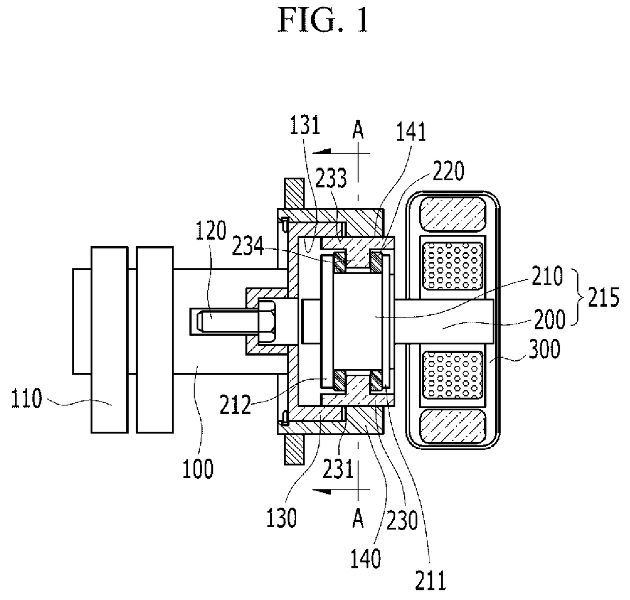
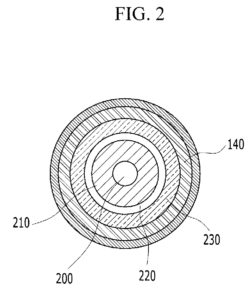
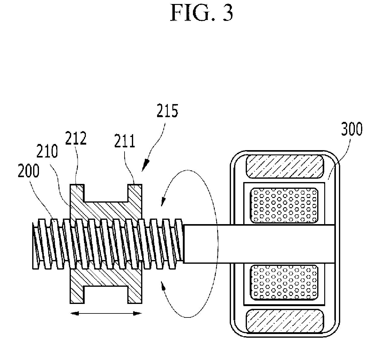
[0030]With reference to FIGS. 1-3, a CVVT apparatus according to various embodiments of the present invention includes a camshaft holder 130, a cam sprocket 140, a leadscrew 230, an operating unit 215, and a motor 300. The camshaft holder 130 is fixed to a camshaft 100 by a fixing element such as a bolt 120, and thus integrally rotate...


PUM


Abstract

Power consumption for maintaining a target valve timing and noise in operation is reduced by a continuously variable valve timing apparatus including a camshaft holder fixed to a camshaft, a cam sprocket, a leadscrew screw-coupled with the camshaft holder and the cam sprocket and is movable so as to rotate the camshaft holder and the cam sprocket in opposite directions, and an operating unit operated by a motor and moves the leadscrew.

Description

CROSS-REFERENCE TO RELATED APPLICATION[0001]This application claims priority to and the benefit of Korean Patent Application No. 10-2010-0110422 filed Nov. 8, 2010, the entire contents of which application is incorporated herein for all purposes by this reference.BACKGROUND OF INVENTION[0002]1. Field of Invention[0003]The present invention relates to a continuously variable valve timing apparatus (CVVT).[0004]2. Description of Related Art[0005]An internal combustion engine is an apparatus that generates power by burning fuel with intake air in a combustion chamber. Such an internal combustion engine is provided with intake valves to take in the air and fuel and exhaust valves to exhaust combustion gas from the combustion chamber. The intake valves and exhaust valves are operated by rotation of camshaft driven by the rotation of crankshaft.[0006]Optimal timing of the intake and exhaust valves depends on various factors such as an engine speed and engine load. In such background, a va...

Claims


Application Information

Patent Timeline
Patent Type & Authority Patents(United States)
IPC IPC(8): F01L1/34
CPCF01L1/34403F01L2820/032
Inventor YANG, JEI CHOONCHOI, BYONG YOUNGKONG, JIN KOOKWOO, SOO HYUNGKIM, JIN SOON
Owner HYUNDAI MOTOR CO LTD
Features
  • R&D
  • Intellectual Property
  • Life Sciences
  • Materials
  • Tech Scout
  • Unparalleled Data Quality
  • Higher Quality Content
  • 60% Fewer Hallucinations
Learn More