Vehicle body rear structure

a rear structure and rear structure technology, applied in the field of rear structure of vehicles, can solve the problems of reducing the unable to achieve the effect of sufficient booming noise reduction effect, and losing the vibration damping effect, so as to reduce the maximum amplitude and torsional vibration, and increase the structural burden near the hinge on the opposite side of the offset direction

Inactive Publication Date: 2013-06-25
SUZUKI MOTOR CORP
View PDF69 Cites 5 Cited by
  • Summary
  • Abstract
  • Description
  • Claims
  • Application Information

AI Technical Summary

Benefits of technology

[0005]The present invention has been made in view of the above circumstances, and accordingly, an object thereof is to provide a vehicle body rear structure capable of reducing booming noise generated at the time of low-speed running while the fuel economy and manufacturing cost are maintained to a reasonable degree.
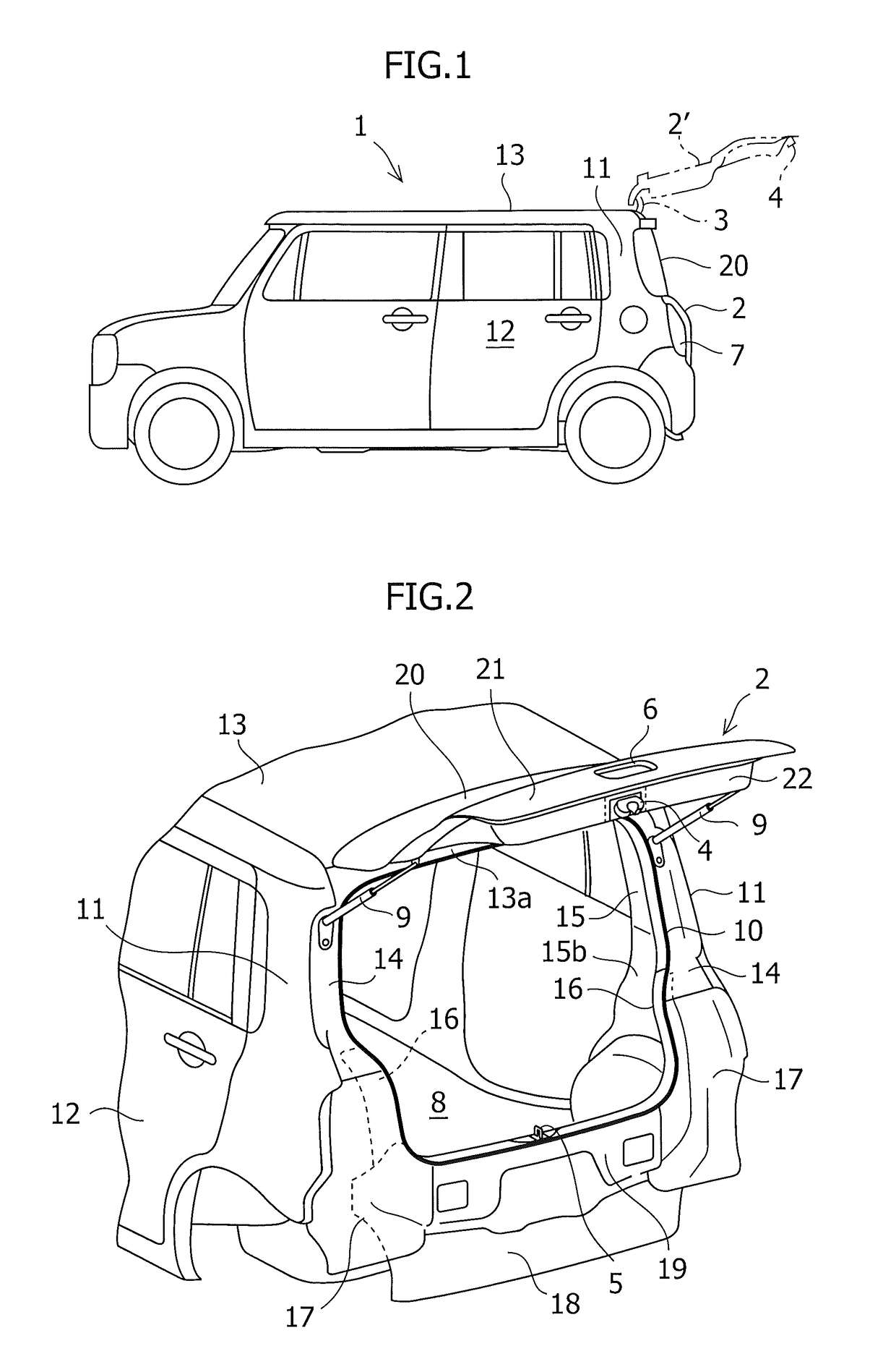
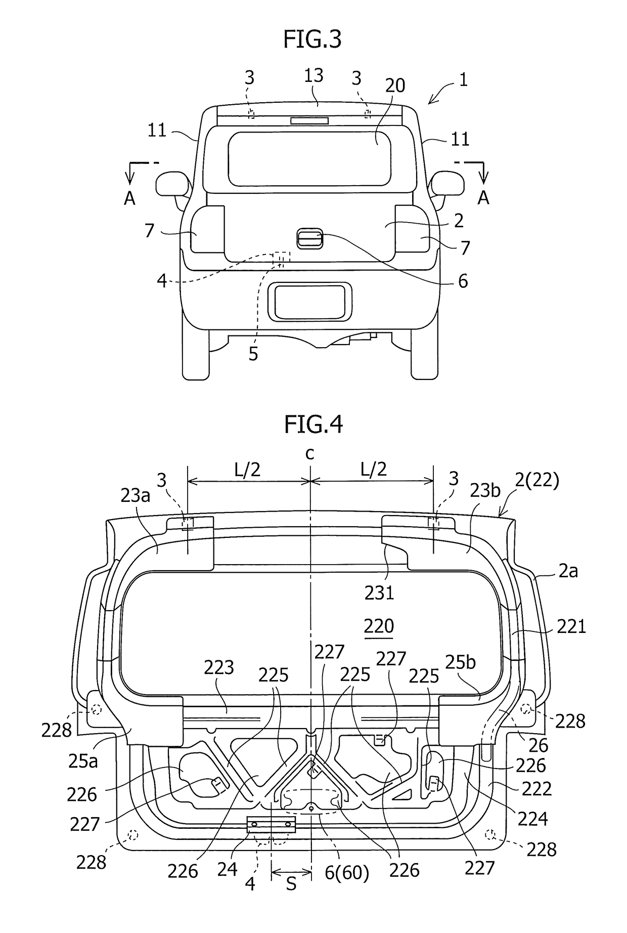
[0007]In the vehicle body rear structure in accordance with the present invention, since the latch (striker) are offset from the center to the side in the vehicle width direction as described above, the inertia weights and natural frequencies on the sides of the back door are asymmetrical with respect to the latch (striker), and torsional vibrations asymmetrical in the right-and-left direction with respect to the latch (striker) are induced on the back door, so that the resonance at a specific frequency is restrained, and the vibration energy transmitted to the back door is diffused and damped because of the structure. Therefore, booming noise can be reduced effectively. Moreover, the above-described configuration can be introduced merely by making a slight design change in the existing configuration, and does not involve an increase in vehicle body weight and an increase in manufacturing cost.
[0010]In a further preferred mode of the present invention, the back door includes a vibration damping structure which is adjacent to the peripheral edge portion located on the opposite side to the offset direction of the latch and is formed of an elastic material interposed between the outer panel and the inner panel. On account of the above-described offset of the latch (striker), an increase of the maximum amplitude in the portion on the opposite side to the offset direction is anticipated. In this mode, however, the provision of a vibration damping structure in this portion is advantageous in restraining or damping the maximum amplitude and torsional vibrations.
[0011]In a still further preferred mode of the present invention, the back door further includes reinforcing members for reinforcing the inner panel upper corner portions ranging from the mounting portions of the two hinges to the side portions of a back window opening; and, of the reinforcing members, one reinforcing member located on the opposite side to the offset direction of the latch is expanded to the center side in the vehicle width direction as compared with the other reinforcing member. On account of the above-described offset of the latch (striker), the structural burden near the hinge on the opposite side of the offset direction increases. In this mode, however, the strengths at the right and left can be balanced by the necessary minimum reinforcement of that portion. Also, this mode is advantageous in restraining the maximum amplitude and torsional vibrations caused by the offset.

Problems solved by technology

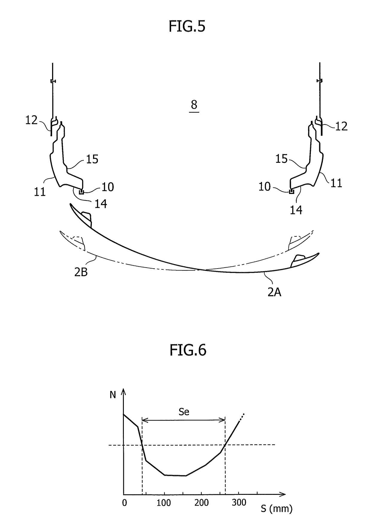
If the offset amount is less than 5%, torsional vibrations are less liable to be induced, so that a sufficient booming noise reducing effect cannot be achieved.
On the other hand, if the offset amount is too large, the maximum amplitude in a portion on the opposite side to the offset direction of back door increases, the vibration damping effect is lost, and the booming noise reducing effect decreases.
In addition, there arises a problem that the structural burden imposed on the hinges by a shock load at the time of the back door opening and closing operation increases.

Method used


Image

  • Vehicle body rear structure
  • Vehicle body rear structure
  • Vehicle body rear structure

Examples


Embodiment Construction

[0018]The present invention now will be described more fully hereinafter in which embodiments of the invention are provided with reference to the accompanying drawings. This invention may, however, be embodied in many different forms and should not be construed as limited to the embodiments set forth herein; rather, these embodiments are provided so that this disclosure will be thorough and complete, and will fully convey the scope of the invention to those skilled in the art.

[0019]The terminology used in the description of the invention herein is for the purpose of describing particular embodiments only and is not intended to be limiting of the invention. As used in the description of the invention and the appended claims, the singular forms “a”, “an” and “the” are intended to include the plural forms as well, unless the context clearly indicates otherwise.

[0020]Unless otherwise defined, all technical and scientific terms used herein have the same meaning as commonly understood by ...


PUM


Abstract

A vehicle body rear structure has a back door for opening and closing a rear opening of a vehicle body, and a latch engageable with and disengageable from a striker fixed in a lower portion of the rear opening, the back door being pivotally connected to an upper portion of the rear opening via two hinges provided so as to be spaced in the vehicle width direction, and the latch being provided in a lower end portion of the back door, the latch and the striker are offset from the center to the side in the vehicle width direction.

Description

CROSS-RELATED APPLICATIONS[0001]This application claims priority from Japanese Patent Application No. 2009-294244; filed Dec. 25, 2009, the disclosure of which is incorporated herein by reference in its entirety.FIELD OF THE INVENTION[0002]The present invention relates to a vehicle body rear structure of a vehicle equipped with a back door, in particular a hatch back type back door, for opening and closing a vehicle body rear opening.BACKGROUND OF THE INVENTION[0003]A hatch back type back door has been used widely for not only vans and wagons but also compact passenger cars because the back door of this type can open a vehicle body rear part widely and can be kept in a jumped-up state, and also access to a passenger room (cargo room) space is easy (refer to JP2005-193827A). For a vehicle equipped with such a back door, it has been known that booming noise is generated at the time of low-speed running. When vibrations of an engine rotating at a low speed close to the resonance freque...

Claims


Application Information

Patent Timeline
Patent Type & Authority Patents(United States)
IPC IPC(8): B60J5/02
CPCB60J5/10E05B77/36E05B79/04E05B83/16
Inventor KISHINO, KIYOHIRO
Owner SUZUKI MOTOR CORP
Why Eureka
Try Eureka