
Apparatus and method for optimizing a vehicle collision preparation response

a technology of collision preparation and apparatus, applied in the field of apparatus and method for optimizing collision preparation response in vehicles, can solve the problems of certain inherent limitations in the types of obstacles

Active Publication Date: 2013-06-25
GM GLOBAL TECH OPERATIONS LLC
View PDF19 Cites 20 Cited by
  • Summary
  • Abstract
  • Description
  • Claims
  • Application Information

AI Technical Summary

Benefits of technology

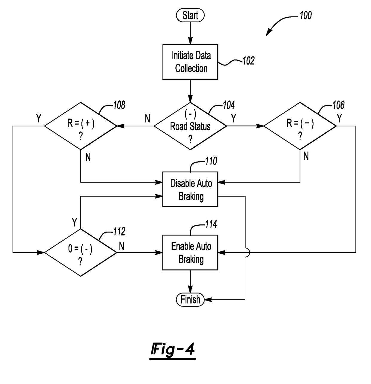
[0005]Accordingly, an apparatus and method are provided for optimizing a vehicle response in a host vehicle having a CPS by classifying the surrounding road and inertial status of the vehicle into a current scenario, referred to hereinafter for simplicity as the vehicle road and inertial scenario or VRIS. An appropriate control response is then determined and executed by an electronic control unit or controller in response to the classified VRIS. In one embodiment, the control response includes the autonomous supplemental braking of the vehicle, which can be achieved by increasing an actual braking level from a baseline braking input level that is input by the driver. In this manner, the apparatus and method compensate for an insufficient braking input level when the classified VRIS so indicates.
[0006]In particular, the apparatus and method seek to discern information about aspects of the surrounding environment by collecting a set of vehicle information describing the presence of any potential obstacles on the road surface using a variety of sensors. In addition to obstacle detection and ranging information, the sensors measure or detect a set of vehicle inertial and / or performance data such as, but not necessarily limited to, vehicle acceleration, velocity, steering angle and / or steering rate, and braking input levels. At least one of the sensors continuously scans the lane boundary or solid line lane marking to determine if and when the vehicle leaves the road surface, a determination that can in one embodiment be verified using an onboard navigation system. The apparatus and method then classify the collective VRIS and tailor an appropriate control response based on the collective set of information provided by the sensors. A vehicle equipped with the apparatus and using the method of the invention can react in a much wider range of circumstances to mitigate the effects of or avoid a collision with an obstacle, while at the same time minimizing instances of false positive recognition of a given VRIS.

Problems solved by technology

However, there are certain inherent limitations in the types of obstacles that can be accurately detected and classified by a radar device.
As a result, under certain circumstances the CPS may take an action, or may forego an action, in response to an inaccurately or less than optimally evaluated collision risk, particularly for certain potential off-road obstacles.

Method used


Image

  • Apparatus and method for optimizing a vehicle collision preparation response
  • Apparatus and method for optimizing a vehicle collision preparation response
  • Apparatus and method for optimizing a vehicle collision preparation response

Examples


Embodiment Construction

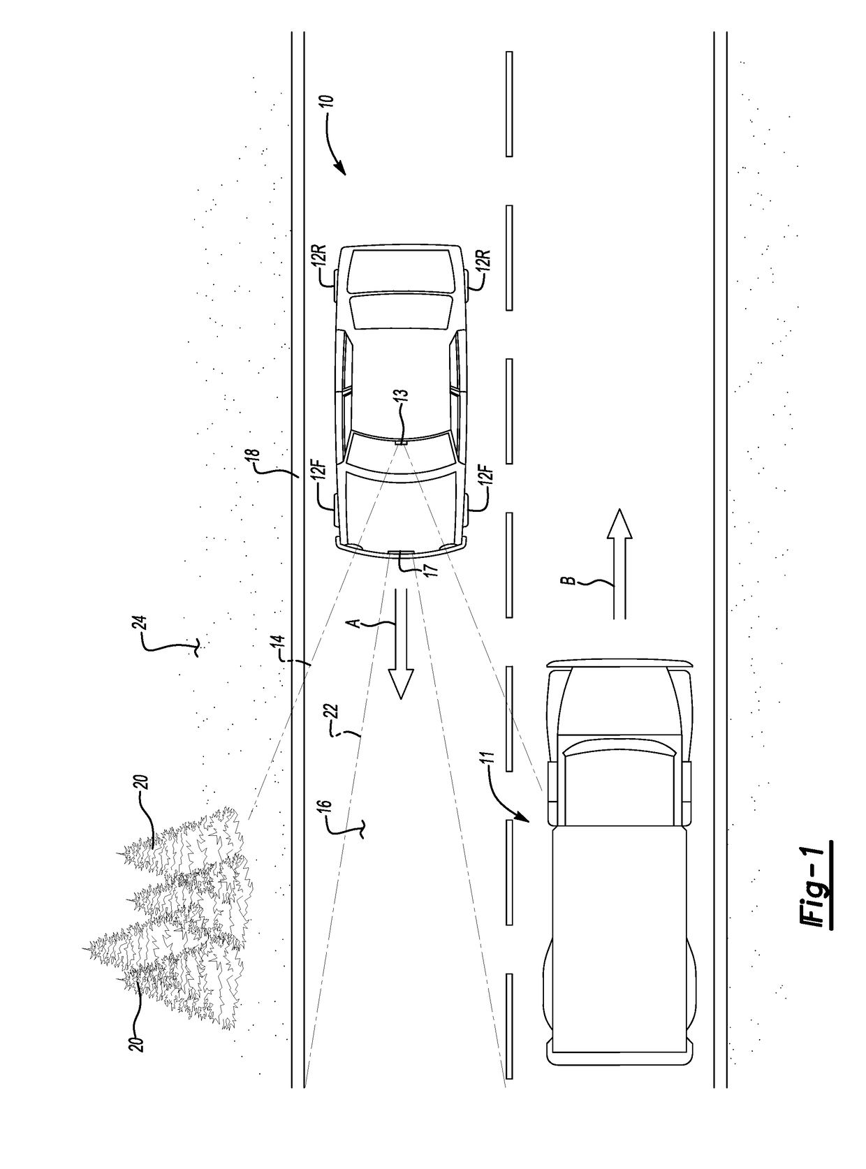
[0014]With reference to the Figures, wherein like reference numerals refer to like or similar components throughout the several figures, and beginning with FIG. 1, a vehicle 10 is traveling in the direction of arrow A along a road surface 16, with the vehicle 10 having a set of respective front and rear road wheels 12F, 12R in contact with the road surface 16. The road surface 16 is exemplified by a paved highway or surface street, with the boundaries or lanes of the road surface 16 being demarked or delimited via a solid line 18 exemplified by the solid white line that ordinarily demarks the outer limits of a paved lane. The solid line 18 separates the edge or boundary of the pavement of the road surface 16 from an adjacent off-road surface 24, such as dirt, grass, mud, gravel, etc.

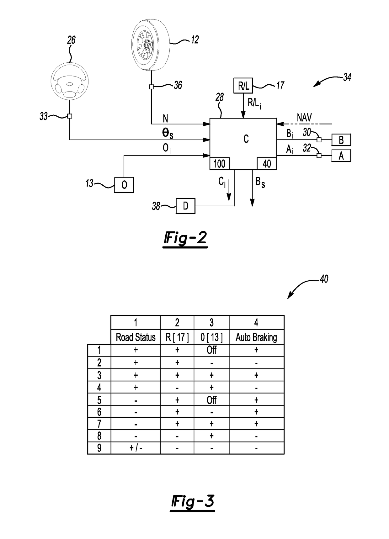
[0015]The vehicle 10 is equipped with a vehicle road and inertial scenario recognition (VRISR) system 34, as shown in FIG. 2, which includes a first sensor 13 and a second sensor 17. The sensors 13, 17 a...


PUM


Abstract

A vehicle has wheels, sensors for generating an input data set, and a controller. The controller is in communication with the sensors, including a first sensor for detecting an obstacle on a road surface in a first manner, and adapted to monitor a boundary of the road surface to determine when the wheels are crossing the boundary. A second sensor detects the obstacle in a second manner, and additional sensors determine inertial data of the vehicle. The controller compares the input data set to calibrated thresholds, and determines an appropriate control response such as autonomous braking based on the results. A method optimizes a collision preparation response in the vehicle by measuring the inertial data, detecting the obstacle using a radar or LiDAR device, and monitoring the boundary using an electro-optical device. A supplemental braking force is automatically applied when the vehicle crosses the boundary while the obstacle is detected.

Description

TECHNICAL FIELD[0001]The present invention relates to an apparatus and method for optimizing a collision preparation response in a vehicle.BACKGROUND OF THE INVENTION[0002]Vehicles equipped with a collision preparation system or CPS utilizes one or more sensors to monitor the path of travel of the vehicle for a potential obstacle, and to ascertain the distance and closing rate to such an obstacle. If the CPS determines that a collision is imminent or likely, various autonomous or semi-autonomous control actions can be executed to thereby minimize the probability of such a collision, or to at least mitigate the effects of a resultant collision. For example, seat belt tension can be automatically adjusted in a limited CPS, and / or an audible alarm can be activated to alert the driver and other vehicle occupants to the imminent collision. In a more advanced CPS, a hydraulic braking system can be stroked or readied so that the braking system can respond more rapidly when the driver ultim...

Claims


Application Information

Patent Timeline
Patent Type & Authority Patents(United States)
IPC IPC(8): G06F7/70G06F19/00G06G7/00G06G7/76
CPCB60T7/22G08G1/16B60T2201/024B60R21/0134B60R2021/01259B60R2021/01272G08G1/165G08G1/166G08G1/167
Inventor ZAGORSKI, CHAD T.
Owner GM GLOBAL TECH OPERATIONS LLC
Learn More