Sanitary hydrant

a sanitary hydrant and hydrant body technology, applied in the direction of water supply installation, drawing-off water installation, transportation and packaging, etc., can solve the problems of not having the desired mass flow rate, affecting the operation of the venturi, and optimizing the flow characteristics, so as to facilitate fluid flow, reduce back pressure, and facilitate the effect of fluid flow

Active Publication Date: 2013-07-02
WCM IND INC
View PDF237 Cites 11 Cited by
  • Summary
  • Abstract
  • Description
  • Claims
  • Application Information

AI Technical Summary

Benefits of technology

[0012]While the use of a venturi is not new to the sanitary yard hydrant industry, the design features of the venturi employed by embodiments of the present invention are unique in the way freeze protection is provided. More specifically, current hydrants employ a system that allows water to bypass a required vacuum breaker. For example, the Hoeptner Freeze Flow Hydrant employs a detachable vacuum breaker and the Woodford Model S3 employs a diverter. Again, fluid diversion is needed so that sufficient fluid flow is achieved for proper venturi functions. The venturi design of sanitary hydrants of the present invention is unique in that the venturi will function properly when water flows through the vacuum breaker or double check backflow preventer-no fluid diversion at the hydrant head is required. This allows the hydrant to work in a way that is far more user friendly, because the hydrant is able to maintain its freeze resistant functionality without requiring the user to open a diverter, for example. Embodiments of the present invention are also environmentally friendly as resources are conserved by avoiding flowing water out of a diverter.
[0014]It is another aspect of the present invention to provide a nozzle having an exit angle that facilitates fluid flow through the venturi. More specifically, the nozzle exit of one embodiment possesses a gradual angle so that fluid flowing through the venturi maintains fluid contact with the surface of the nozzle and laminar flow is generally achieved. In one embodiment the exit angle is between about 4 to about 5.6 degrees. For example, nozzle exit having very gradual surface angle, e.g. 1-2 degrees, will evacuate the reservoir more quickly, but would require an elongated venturi. Thus, an elongated venturi may be used to reduce back pressure associated with the venturi, but doing so will add cost. The nozzle inlet may have an angle that is distinct from that of the exit to facilitate construction of the venturi by improving the machining process.

Problems solved by technology

One difficult part of optimizing the flow characteristics to achieve these results is determining the nozzle diameter.
That same change, however, affects the operation of the venturi.
For example, hydrants with a nozzle diameter of 0.125 inches will provide acceptable reservoir evacuation but would not have the desired mass flow rate.
Thus, an elongated venturi may be used to reduce back pressure associated with the venturi, but doing so will add cost.

Method used


Image

  • Sanitary hydrant
  • Sanitary hydrant
  • Sanitary hydrant

Examples


Embodiment Construction

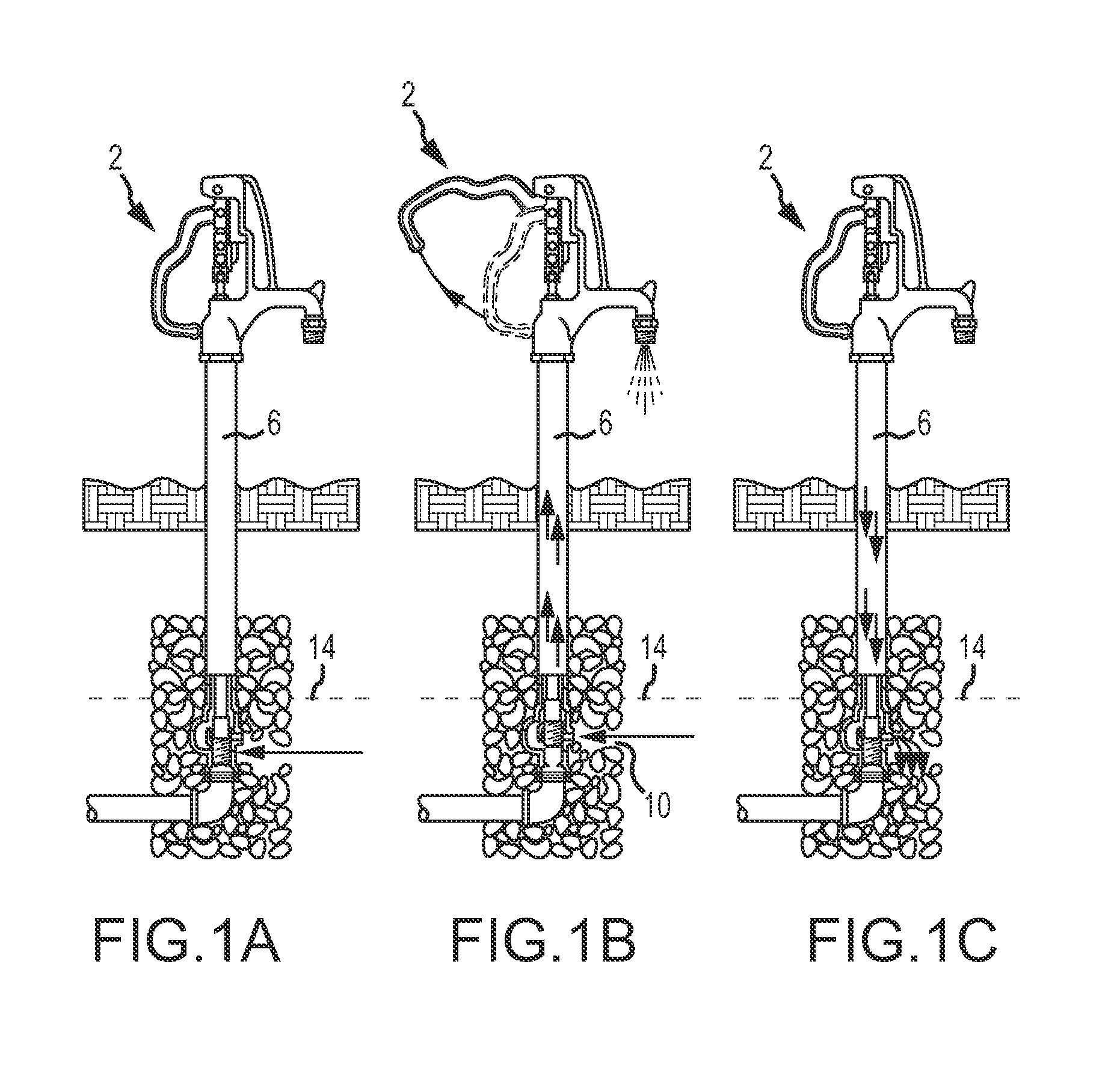
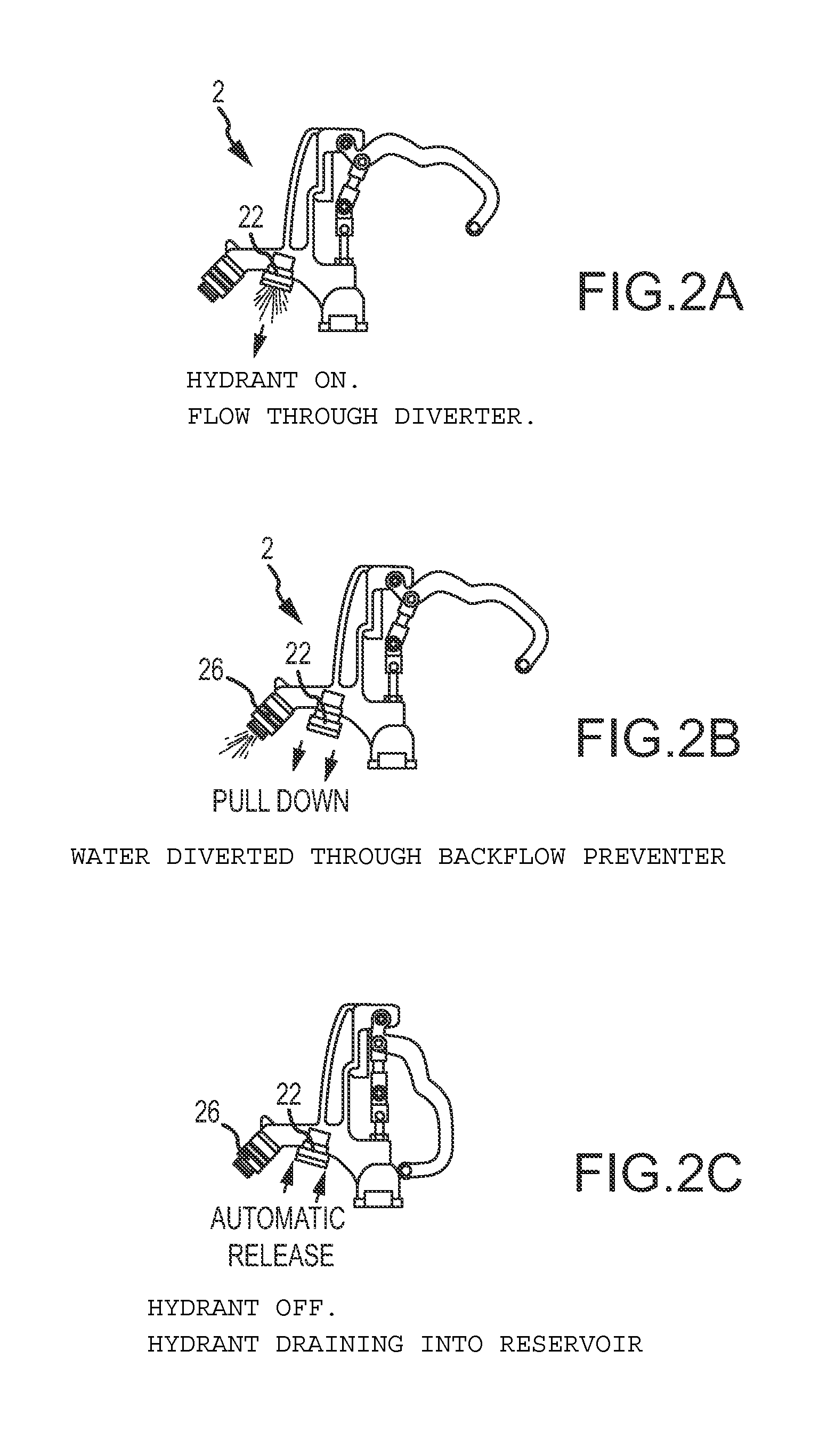
[0042]The venturi 18 and related components used in the hydrants of the prior art is shown in FIGS. 3 and 4 and functions when the hydrant issued in conjunction with a vacuum breaker and a diverter. The diverter is needed to allow the venturi to work properly in light of the flow obstructions associated with the vacuum breaker. A typical on / off cycle for this hydrant (see also FIG. 2) requires that the user open the hydrant to cause water to exit the diverter 22 and not the vacuum breaker 26. As the water flows out of the diverter 22, a vacuum is created that draws water through a siphon tube 30 and check valve 34, which evacuates the reservoir (not shown). Flowing water through the diverter 22 for about 30 to 45 seconds will generally evacuate the reservoir. Next, as shown in FIG. 2, the diverter 22 is pulled down to redirect the water out of the vacuum breaker 26. The vacuum breaker 26 allows the hydrant 2 to be used with an attached hose and / or a spray nozzle as the vacuum breake...


PUM


Abstract

A freeze resistant sanitary hydrant is provided that employs a reservoir for storage of fluid under the frost line or in an area not prone to freezing. To evacuate this reservoir, a venturi is provided that is able to function in hydrant systems that employ a vacuum breaker.

Description

[0001]This patent application claims the benefit of U.S. Provisional Patent Application Ser. No. 61 / 313,902, filed Mar. 15, 2010, and U.S. Provisional Patent Application Ser. No. 61 / 313,918, filed Mar. 15, 2010, the entire disclosures of which are incorporated by reference herein. This application is also related to U.S. Patent Application Publication No. 20090288722, U.S. Pat. No. 7,472,718, and U.S. Pat. No. 7,730,901, the entire disclosure of which are incorporated by reference herein.FIELD OF THE INVENTION[0002]Embodiments of the present invention are generally related to contamination proof hydrants that employ a venturi that facilitates transfer of fluid from a self-contained water storage reservoir.BACKGROUND OF THE INVENTION[0003]Hydrants typically comprise a head interconnected to a water source by way of a vertically oriented standpipe that is buried in the ground or interconnected to a fixed structure, such as a roof. To be considered “freeze proof” hydrant water previous...

Claims


Application Information

Patent Timeline
Patent Type & Authority Patents(United States)
IPC IPC(8): E03B9/02
CPCE03B9/14Y10T137/5327Y10T137/0318Y10T137/5444Y10T137/87338Y10T137/5497E03B9/027
Inventor BALL, WILLIAM T.PILARCZYK, ERICJACKSON, CODY
Owner WCM IND INC
Why Eureka
Try Eureka