Downspout drain connection and filter

a technology of drain connection and filter, which is applied in the direction of water cleaning, filtration separation, and separation processes, etc., can solve the problems of preventing the proper flow of water to the downspouts and through the gutter system, damage to and around the structure, erosion and foundation problems, etc., to facilitate the removal of rain from the structure

Active Publication Date: 2013-07-02
OMNIMAX INT LLC
View PDF53 Cites 15 Cited by
  • Summary
  • Abstract
  • Description
  • Claims
  • Application Information

AI Technical Summary

Benefits of technology

[0019]Yet still another object of the present invention is to provide a downspout drain filter that is capable of a

Problems solved by technology

A known problem with gutter systems is debris, such as flora, including foliage, berries, needles, nuts, flowers, and the like, and fauna, including nests, remains and the like, can enter into a gutter system causing clogging and preventing the proper flow of water to the downspouts and through the gutter system.
The gutter covers have drawbacks when a downspout from the upper roof of a building directs water to the lower roof or during heavy rain periods.
This can cause d

Method used


Image

  • Downspout drain connection and filter
  • Downspout drain connection and filter
  • Downspout drain connection and filter

Examples


Embodiment Construction

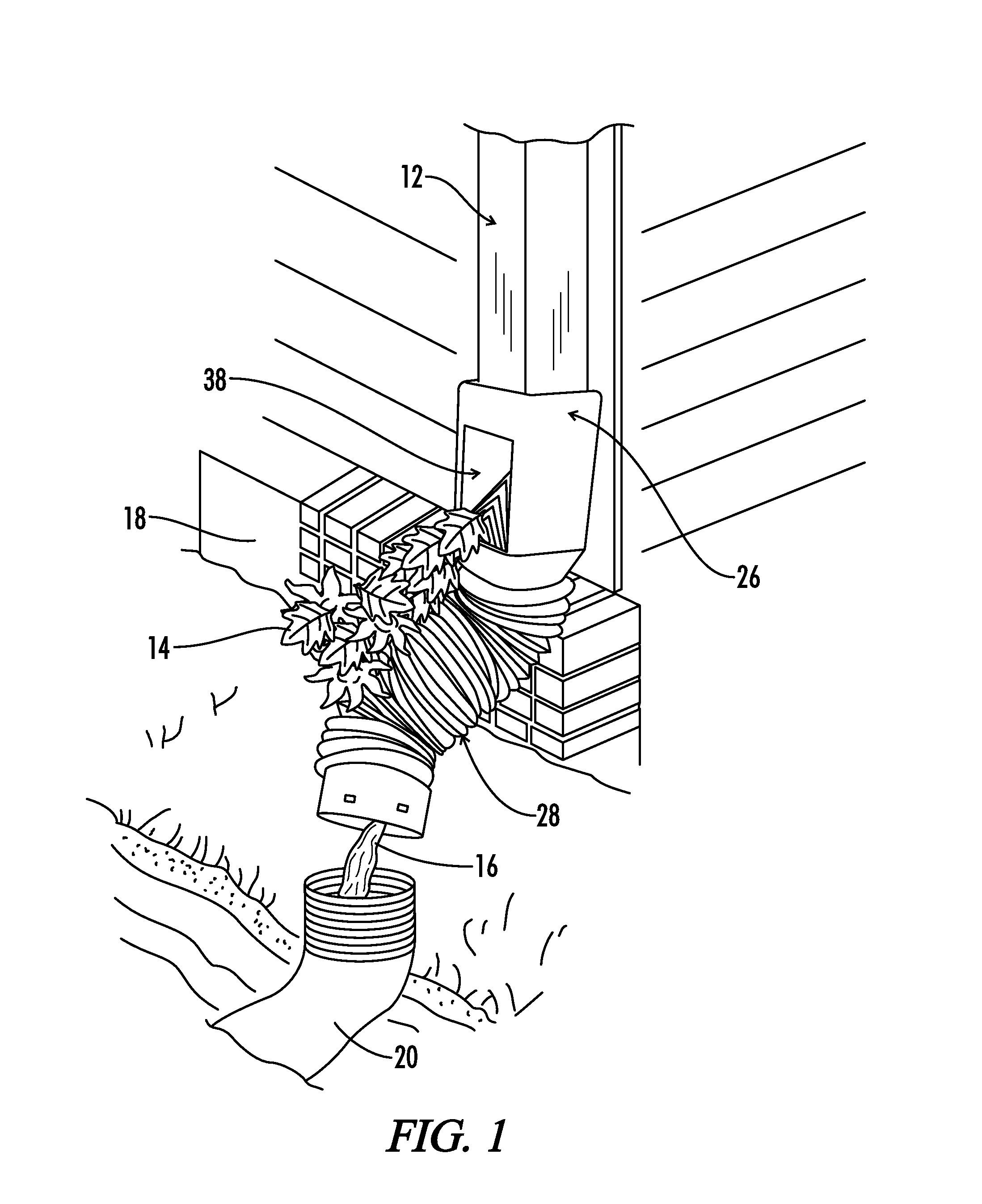
[0039]Referring generally now to FIGS. 1-17B, a downspout drain filter is shown and generally designated by the numeral 10. The drain filter 10 is used in conjunction with a rain gutter downspout 12 to remove debris 14 from the fluid flow path 16. The fluid flow path 16 preferably moves rain that collects on the structure 18, including the roof of the structure 18. The drain filter 10 can be used with a fluid flow element 20 such as an underground rainwater dispersing system.

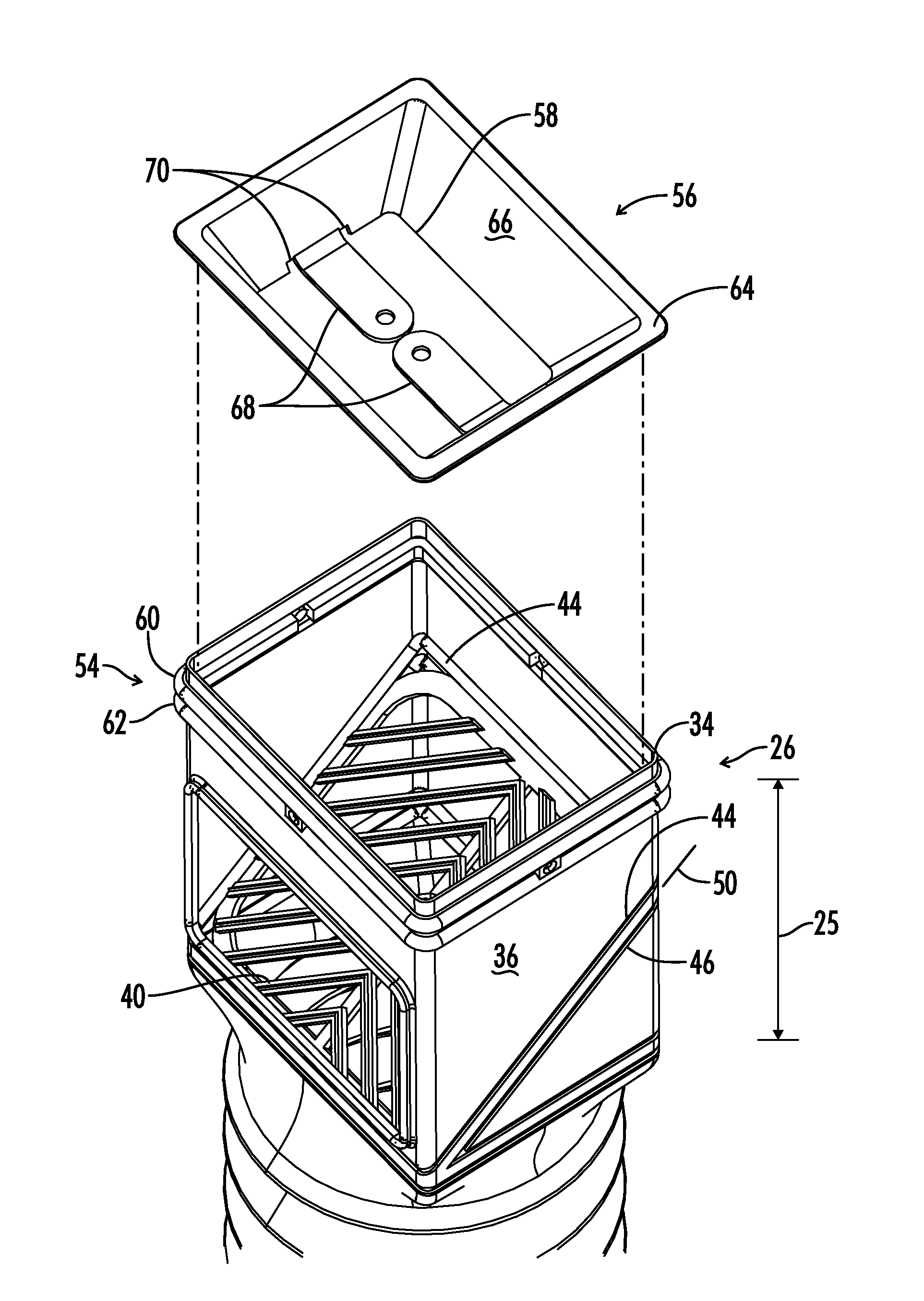
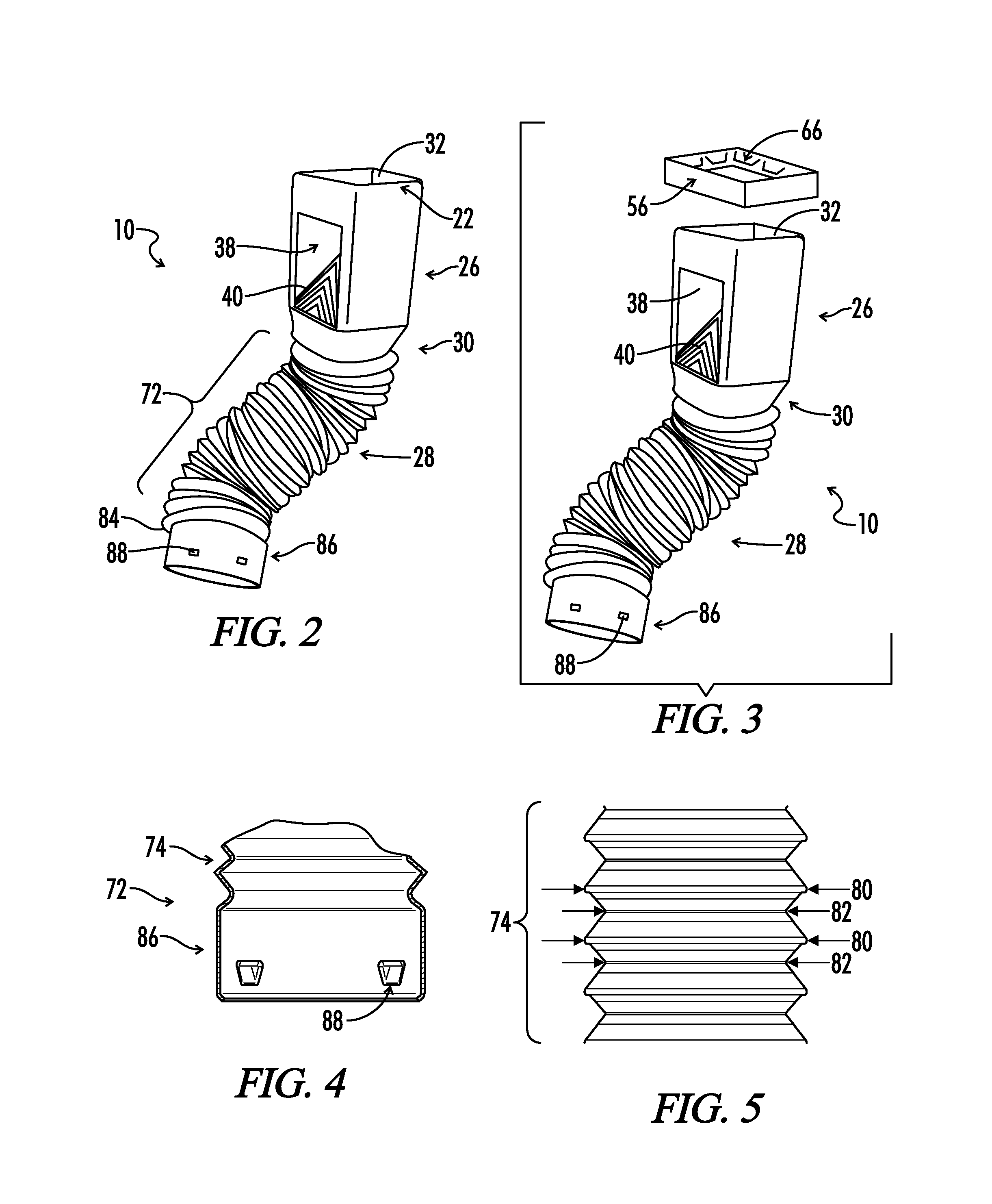
[0040]As best seen in FIGS. 2, 3, and 11, the drain filter 10 comprises an elongated housing 22 having an axis 24, a top portion 26, a bottom portion 28 and a transition portion 30 connecting the top portion 26 to the bottom portion 28.

[0041]The top portion 26, which can be described as an intake section 26, includes an intake opening 32 shaped to accept an end of the rain gutter downspout 12. An intake section wall 36 of the intake section 26 defines a top portion perimeter 34, which can be described as an inta...


PUM

PropertyMeasurementUnit
Volumeaaaaaaaaaa
Volumeaaaaaaaaaa
Volumeaaaaaaaaaa

Abstract

Included in this disclosure is a downspout drain filter for rain gutter downspouts. The downspout drain filer comprises elongated housing having an axis, a top portion, and a bottom portion. A transition portion connects the top portion to the bottom portion. The top portion includes an intake opening, a top portion perimeter, a debris opening, a filter attachment location, and a downspout attachment location. The downspout attachment location includes a flexible collar that defines a downspout attachment location perimeter that is less than the top portion perimeter. The bottom portion includes a flexible collapsible body that extends from the transition portion. A connection end is positioned opposite the transition portion as a part of the bottom portion. A filter is positioned in the top portion to direct debris out the debris opening and to permit liquid to pass to the bottom portion.

Description

CROSS-REFERENCES TO RELATED APPLICATIONS[0001]This application claims benefit of the following Provisional Patent Applications which are hereby incorporated by reference: U.S. Provisional Application No. 61 / 215,255 filed May 4, 2009 entitled “A Landscape Drain Filter,” and U.S. Provisional Application No. 61 / 285,477 filed Dec. 10, 2009 entitled “Low Profile Downspout Extension And Landscape Drainage Assembly.”[0002]A portion of the disclosure of this patent document contains material that is subject to copyright protection. The copyright owner has no objection to the reproduction of the patent document or the patent disclosure, as it appears in the U.S. Patent and Trademark Office patent file or records, but otherwise reserves all copyright rights whatsoever.[0003]All patents and publications described or discussed herein are hereby incorporated by reference in their entirety.BACKGROUND OF THE INVENTION[0004]The present disclosure relates generally to a filtering device, and more pa...

Claims


Application Information

Patent Timeline
IPC IPC(8): E04D13/076E04D13/08B01D35/02
CPCE04D13/0767B01D35/02E04D13/08E04D2013/086E04D13/0641E04D13/0645E04D13/068E04D13/076E04D2013/0806F16L25/14
Inventor SMITH, JEFFREY E.
Owner OMNIMAX INT LLC
Why Eureka
Try Eureka