Probe tracking using multiple tracking methods

a technology of multiple tracking methods and probes, applied in the field of position sensing of probes, can solve the problems of inability or desirable real-time three-dimensional imaging, and achieve the effect of reducing the first cost function

Active Publication Date: 2013-07-02
BIOSENSE WEBSTER (ISRAEL) LTD
View PDF13 Cites 110 Cited by
  • Summary
  • Abstract
  • Description
  • Claims
  • Application Information

AI Technical Summary

Benefits of technology

[0011]applying a model of known mechanical properties of the probe to the respective apparent locations so as to minimize a first cost function with respect to shapes that can be assumed by the probe in the body;
[0013]minimizing a second cost function with respect to differences between the apparent locations and the preliminary coordinates; and
[0024]In a disclosed embodiment the method further includes applying an adjustment parameter to the preliminary coordinates to formulate parameterized preliminary coordinates, minimizing the second cost function includes computing differences between the apparent locations and the parameterized preliminary coordinates so as to determine a value of the adjustment parameter, and generating the corrected coordinates includes applying the value of the adjustment parameter to the preliminary coordinates to evaluate the parameterized corrected coordinates.
[0029]apply a model of known mechanical properties of the probe to the respective apparent locations so as to minimize a first cost function with respect to shapes that can be assumed by the probe in the body,
[0035]apply a model of known mechanical properties of the probe to the respective apparent locations so as to minimize a first cost function with respect to shapes that can be assumed by the probe in the body;

Problems solved by technology

In most situations, however, real-time three-dimensional imaging is not possible or desirable.

Method used


Image

  • Probe tracking using multiple tracking methods
  • Probe tracking using multiple tracking methods
  • Probe tracking using multiple tracking methods

Examples


Embodiment Construction

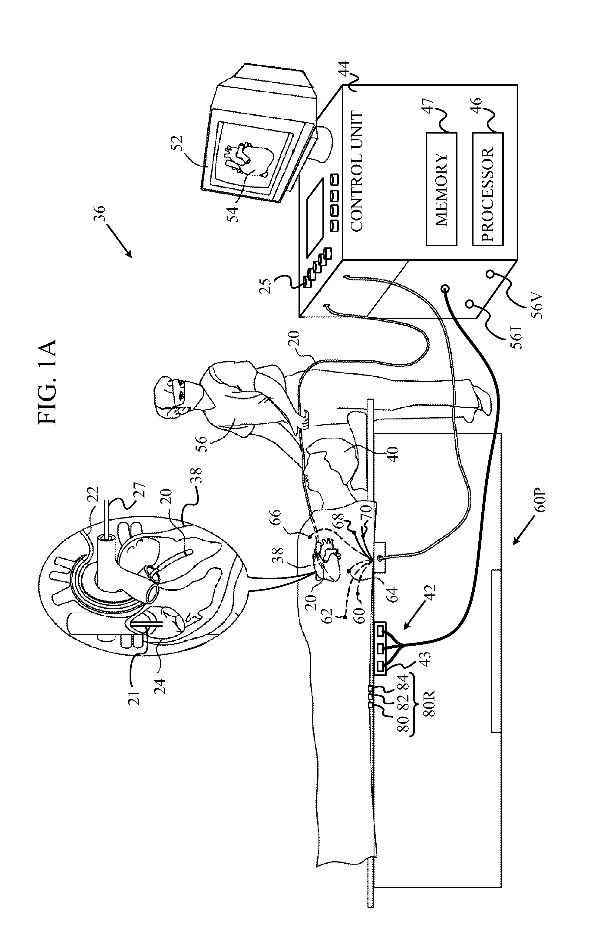
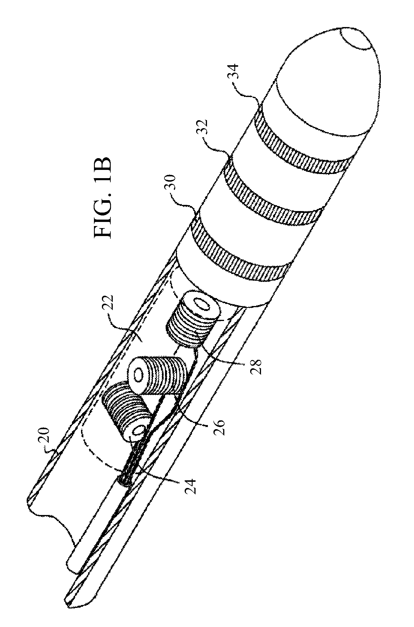
[0049]In embodiments of the present invention, a first tracking sub-system is calibrated using a second, more accurate, tracking sub-system. Either sub-system may be used for measurement of the location and orientation of a probe, herein by way of example assumed to be a catheter tip, within the body of a patient. Both sub-systems are operated in a calibration phase, but only the first sub-system is used in a tracking phase.

[0050]The first sub-system generates currents between an electrode on the catheter tip and a number of conducting elements positioned on or within the body, so forming a current distribution. The location of the electrode is calculated from the current distribution. The second sub-system may be any location tracking system that operates on a different principle to that of the first sub-system. In the calibration phase, relations are formed between the results of the two sub-systems.

[0051]In the tracking phase, i.e., when the first sub-system is used by itself to ...


PUM


Abstract

A method, including: receiving an input indicative of respective apparent locations of a plurality of points disposed along a length of a probe inside a body of a subject, and applying a model of known mechanical properties of the probe to the respective apparent locations so as to minimize a first cost function with respect to shapes that can be assumed by the probe in the body. The method further includes choosing a shape responsively to the minimized first cost function and determining preliminary coordinates of the apparent locations responsively to the shape, minimizing a second cost function with respect to differences between the apparent locations and the preliminary coordinates, and generating corrected coordinates of the points along the length of the probe based on the minimized second cost function.

Description

FIELD OF THE INVENTION[0001]The present invention relates generally to sensing the position of an object placed within a living body, and specifically to position sensing of a probe in a living body using multiple measuring parameters.BACKGROUND OF THE INVENTION[0002]A wide range of medical procedures involve placing objects, such as sensors, tubes, catheters, dispensing devices, and implants, within the body. Real-time imaging methods are often used to assist doctors in visualizing the object and its surroundings during these procedures. In most situations, however, real-time three-dimensional imaging is not possible or desirable. Instead, systems for obtaining real-time spatial coordinates of the internal object are often utilized.[0003]U.S. Patent Application 2007 / 0016007, to Govari et al., whose disclosure is incorporated herein by reference, describes a hybrid magnetic-based and impedance-based position sensing system. The system includes a probe adapted to be introduced into a...

Claims


Application Information

Patent Timeline
Patent Type & Authority Patents(United States)
IPC IPC(8): A61B5/00
CPCA61B5/063A61B5/061A61B2019/5265A61B2019/5251A61B2034/2051A61B2034/2065
Inventor BAR-TAL, MEIROSADCHY, DANIEL
Owner BIOSENSE WEBSTER (ISRAEL) LTD
Why Eureka
Try Eureka