Channeling gas flow tube

a gas flow tube and channeling technology, applied in the field of tubes, can solve the problems of reducing efficiency, reducing efficiency, affecting the effect of drag, etc., and achieve the effect of increasing the magnetic flux, increasing the electric current, and increasing the forward momentum

Inactive Publication Date: 2013-07-09
PARALLAXIAL INNOVATION
View PDF35 Cites 17 Cited by
  • Summary
  • Abstract
  • Description
  • Claims
  • Application Information

AI Technical Summary

Benefits of technology

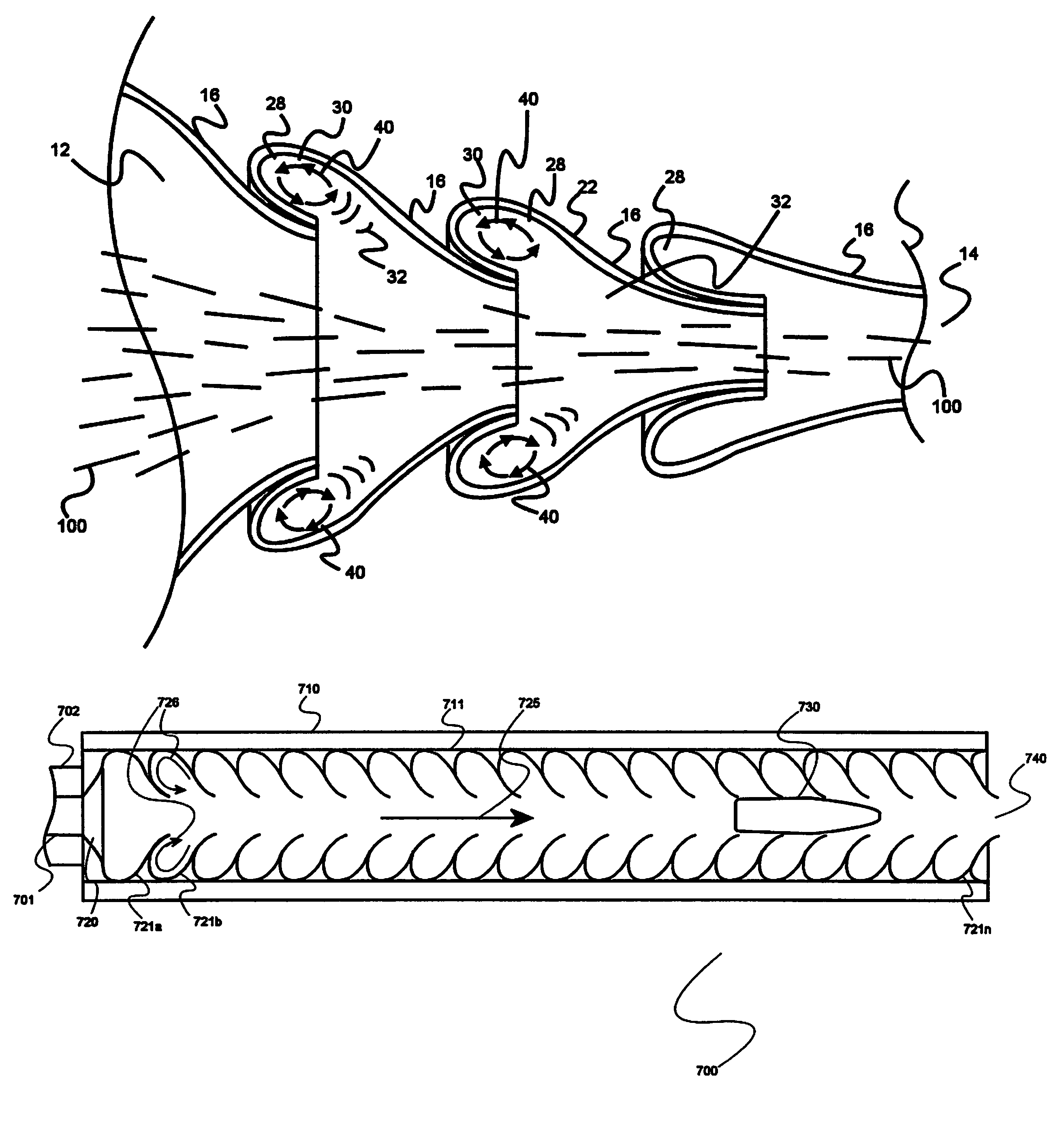
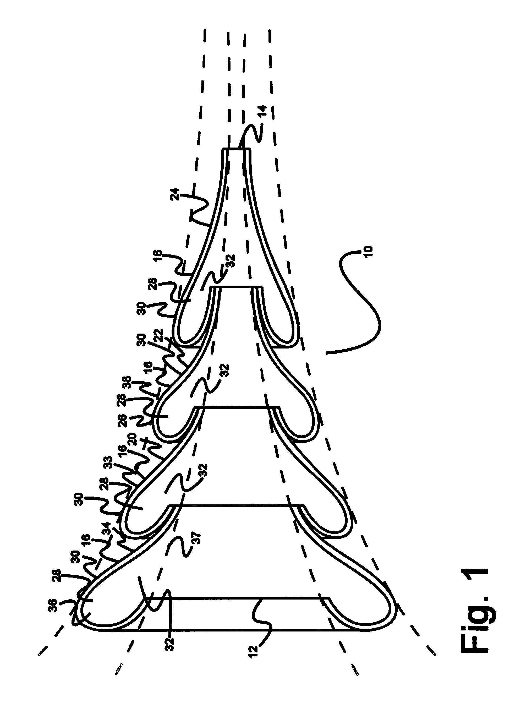
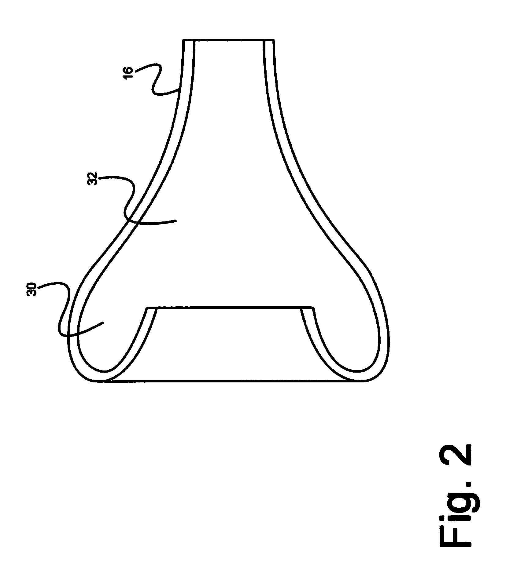
[0007]A tube includes a series of guides with each successive guide smaller than a next prior guide. The tube thus forms an effective funnel ending at a tube exit end smaller than a tube entry end. The guides are arranged longitudinally with a smaller end extending toward the exit end extending into a larger end of a next adjacent guide. The larger end of the next adjacent guide extends past the smaller end of its prior flow guide and loops back to taper into smooth connection with the outside of the smaller end of that prior flow guide therein creating a cavity in the guide. In effect, various embodiments of the invention serve to employ turbulence as a work function to achieve flow and thrust structure modification, by idealizing fluid dynamic interactions into organized geometric structures in a flow continuum. When the flow / waveguide is geometrically configured in a fashion consistent with and sympathetic to the ideal geometry of the fluid dynamic instability being groomed, the flow vector forces also become organized and may be directed in a manner that provides allowing an engineered flow continuum protocol providing a benefit such as energy efficiency or shock wave absorption and translation to a fluid continuum with a higher degree of forward momentum. Put another way, the invention provides an effect analogous to Faraday's Law, in which changes in a magnetic field induce electric current through a conductor; in the case of embodiments of the invention, fluctuations of a flow continuum are employed to accelerate fluid current through a conduit or across a surface treated according to the invention. In Faraday's Law, greater magnetic flux increases electric current; according to the invention, greater pulse / noise / flux amplitude provides more fluid acceleration and laminar flow (or a higher degree of forward momentum).
[0009]Gas passing rapidly past the guide cavities induces a domain of axial fluid movement close to the continuous curved inner line, allowing forces resulting from fluid expansion to enter a cavity, whereupon it is allowed to expand, rotate, reflect and mix. That is, momentum-accumulating rotor effects causes a Bernoulli effect reducing pressure within the cavities. Because the mouth of the guides are large, a vortex is induced□ from a shearing interface between gases within the cavity and the main flow of gas moving down the tube translating kinetic energy from the main flow into the vortex of a respective cavity as well as shedding the over-spilling or shedding portion in a relaying effect to successive downstream cavities.
[0012]According to another embodiment, the tube further comprises a plenum between the outer rigid tube wall and a plurality of outer surfaces of the plurality of adjoining adjacent guides, the plenum further comprising a plurality of air inlets proximate to the inlet end of the tube, and an outlet nozzle at the exit end of the tube which is adapted to receive exhaust gas as it exits the tube. The passage of high-speed exhaust gases through the outlet nozzle causes a pressure drop that pulls in ambient air from the plenum, the flow of air from the air inlets through the plenum to the outlet nozzle acting to cool the external surface of the tube.

Problems solved by technology

Other examples where fluid flow may have deleterious effects include, but are not limited to, firearms (shock waves in barrels reduces kinetic energy of projectile fired and causes extreme noise), projectile flight (drag on projectile reduces range and may destabilize flight), aircraft wings and other airfoils (drag reduces efficiency and turbulence may adversely impact left generated by an airfoil), terrestrial vehicles (drag reduces efficiency), and jet engines (again, drag from fluid flows reduces efficiency).

Method used


Image

  • Channeling gas flow tube
  • Channeling gas flow tube
  • Channeling gas flow tube

Examples


Embodiment Construction

[0029]The inventor has conceived, and reduced to practice, a channeling gas flow tube that addresses the challenges and problems in the art outlined above. Various techniques will now be described in detail with reference to a few example embodiments thereof, as illustrated in the accompanying drawings. In the following description, numerous specific details are set forth in order to provide a thorough understanding of one or more aspects and / or features described or referenced herein. However, it will be apparent to one skilled in the art, that one or more aspects and / or features described or referenced herein may be practiced without some or all of these specific details. In other instances, well known process steps and / or structures have not been described in detail in order to not obscure some of the aspects and / or features described or reference herein.

[0030]One or more different inventions may be described in the present application. Further, for one or more of the inventions ...


PUM


Abstract

A tube for moving gas between an entry end into which gas is introduced and an exit end through which gas exits the tube, the tube comprising a plurality of adjoining adjacent□ guides, each guide comprising an outer half of a smoothly-curved, modified torus, and an outer rigid tube wall. Each guide forms an internal cavity with a cavity mouth opening into an inner portion of the tube, the cavities shaped such that a vortex forms within each of the cavities as gas passes through the tube, and the flow of fluid in the tube is unidirectional and axial from the entry end to the exit end.

Description

RELATED APPLICATIONS[0001]This application is a continuation-in-part of U.S. patent application Ser. No. 12 / 238,253, titled “CHANNELING GAS FLOW TUBE”, filed on Sep. 25, 2008 and issuing on Jul. 3, 2012 as U.S. Pat. No. 8,210,309, the entire specification of which is incorporated herein by reference.BACKGROUND OF THE INVENTION[0002]1. Field of the Invention[0003]This invention pertains to tubes through which a fluid may move, and more particularly, to such a tube that channels gases, and articles suspended in a gas flow, centrally or axially down the tube.[0004]2. Discussion of the State of the Art[0005]Backpressure in engine exhausts is a well-known phenomenon that robs energy from the engine. Mufflers and catalytic converters contribute to the backpressure. It is a primary object of the present invention to provide a tube functional as an exhaust pipe that reduces backpressure and reduces or eliminates the need for a muffler.[0006]More generally, many devices known in the art rely...

Claims


Application Information

Patent Timeline
Patent Type & Authority Patents(United States)
IPC IPC(8): F41A21/30F01N1/08F01N1/00F41A21/00
CPCF01N1/026F01N13/082F16L9/22F41A21/30F01N2470/20F01N2490/155F01N2490/16F01N2470/24Y10T137/2093
Inventor SCHLOSSER, THOMAS GEORGE
Owner PARALLAXIAL INNOVATION
Why Eureka
Try Eureka