Armrest device

a technology for armrests and armrests, which is applied in the direction of chairs, vehicle components, vehicle arrangements, etc., can solve the problems of increased assembly man-hour requirements, difficulty in meeting weight saving requests, and increased costs, so as to reduce assembly man-hour requirements, reduce the required cost of armrest devices, and save weight

Inactive Publication Date: 2013-07-09
TOKAI CHEM IND CO LTD +1
View PDF19 Cites 5 Cited by
  • Summary
  • Abstract
  • Description
  • Claims
  • Application Information

AI Technical Summary

Benefits of technology

[0065]As described above, the present invention is one in which the stationary-side first ratchet teeth are formed on a ratchet member that is made separately from and independently of the armrest body, whereas the armrest body is made of resin and the second ratchet teeth are molded integrally with that resinous armrest body at the time of molding the armrest body.
[0066]Therefore, in accordance with the present invention, it is not necessarily required to provide a member for the second ratchet teeth separately from and independently of the armrest body. Thus, not only it is possible to make the quantity of components part, which are required for an armrest device, less, but also it is not needed to assemble that member comprising the second ratchet teeth with the armrest body in a state of rotating integrally with the armrest body, thereby making it possible to cut down the assembly man-hour requirement on that occasion.
[0067]Thus, it is possible to reduce the required costs for an armrest device.
[0068]Moreover, since it is not needed to assemble a ratchet member comprising the second ratchet teeth with the armrest body, it cannot be needed to provide a fit structure for the assembly, either. Therefore, a space for that assembly can also be cut down, and so it is possible to downsize the assembled section between the ratchet mechanism and the armrest body.
[0069]In the present invention, it is possible to make an armrest device lightweight as a whole remarkably, because the armrest body, which occupies a major portion of the armrest device, is made of resin.
[0070]In addition, since it is not needed to form the second ratchet teeth on a member that is made separately from and independently of the armrest body, a member for the second ratchet teeth, and furthermore a fastening member for fastening that member can be cut back, and hence it is possible to intend weight saving much more.

Problems solved by technology

However, in the case of armrest devices being classified with this type, the following problems arise: not only the operation has become heavy upon operating the armrest to rotate because a metallic and large-sized locking spring with heavy weight is used so that the resulting armrest device itself has turned into one with heavy weight; but also it is difficult to meet the request of weight saving especially when being used in the application for a seat of automobile for which weight saving has been strongly required recently.
However, in the case of conventional armrest devices being classified with a ratchet style of this sort, involving those being disclosed in these Patent Literature No. 4 and Patent Literature No. 2, since a ratchet member comprising the stationary-side first ratchet teeth, and another ratchet member comprising the movable-side second ratchet teeth are constituted of distinctive members, which are made separately from or independently of the armrest, respectively, they have problems like below that come with this construction.
Moreover, since the drawback results in entailing an assembly step of assembling one of the ratchet members with the armrest body, the required assembly man-hour requirement has got greater, and thereby costs have become higher as being accompanied by this drawback.
However, if such is the case, since a structure for fitting them together, and a space for that should be provided, these drawbacks entail such a drawback that the assembled section has become large-sized between the ratchet mechanism and the armrest body.
In addition, if rattling should have occurred at the assembled section when such an assembly structure is made, there might possibly arise such a fear that the armrest body rattles about when a user applies a load to the armrest body.
Then, that drawback has hindered the armrest body from moving smoothly, and moreover has deteriorated the feeling of using the resulting armrest.Patent Literature No. 1: Japanese Patent Gazette No. 4,089,386;Patent Literature No. 2: Japanese Patent Gazette No. 4,094,421;Patent Literature No. 3: Japanese Patent Gazette No. 4,087,635;Patent Literature No. 4: Published Japanese Translation of PCT Application Gazette No. 2003-520, 156; andPatent Literature No. 5: Japanese Unexamined Patent Publication (KOKAI) Gazette No. 2007-283, 908

Method used


Image

  • Armrest device
  • Armrest device
  • Armrest device

Examples


Embodiment Construction

[0138]Subsequently, an embodiment mode according to the present invention will be explained in detail based on the drawings.

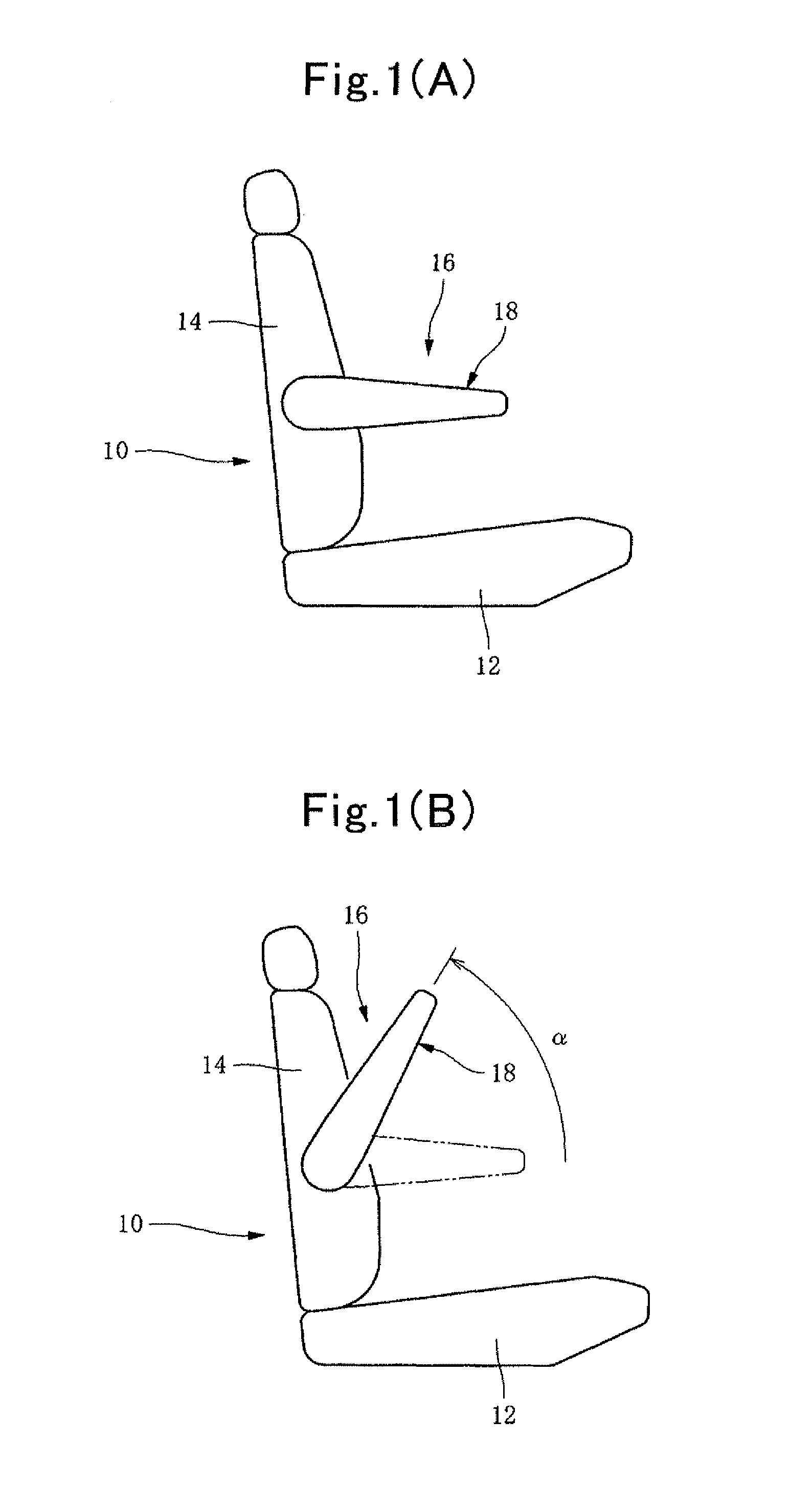
[0139]In FIG. 1, 10 is a seat of automobile, 12 is the seated portion, 14 is the seat back, and 16 is an armrest device that is installed to that seat back 14.

[0140]18 is an armrest making a major part of that armrest device 16. The armrest 18 is made herein so that the angular position at the time of use (hereinafter simply labeled as “angle”) is adjustable between the substantially-horizontal rotational lower limit shown in FIG. 1(A) and the use-range upper limit shown in FIG. 1(B) where the armrest 18 rotates upward by an angle α (e.g., by 60° herein) beyond the former.

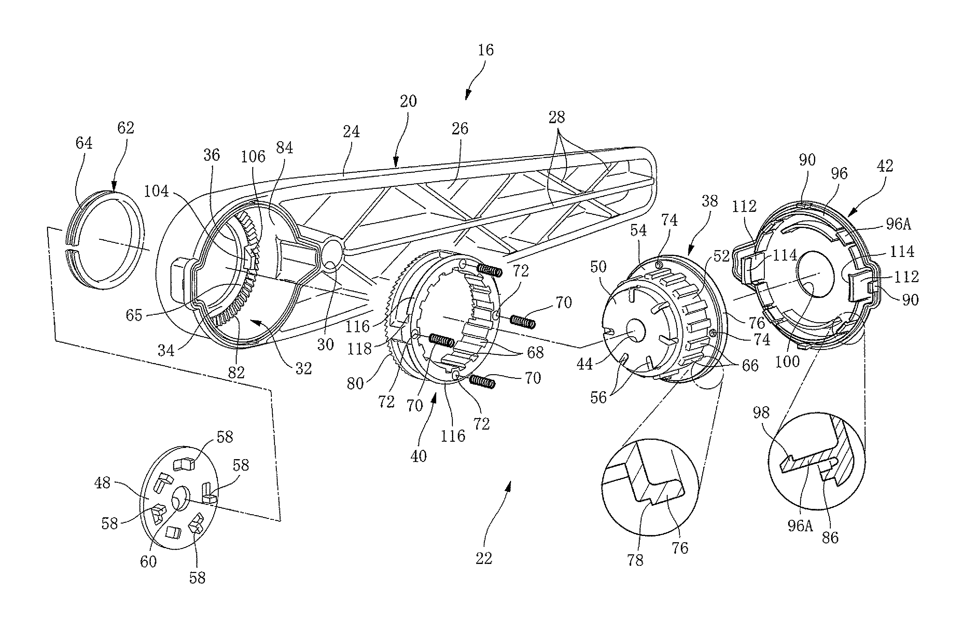
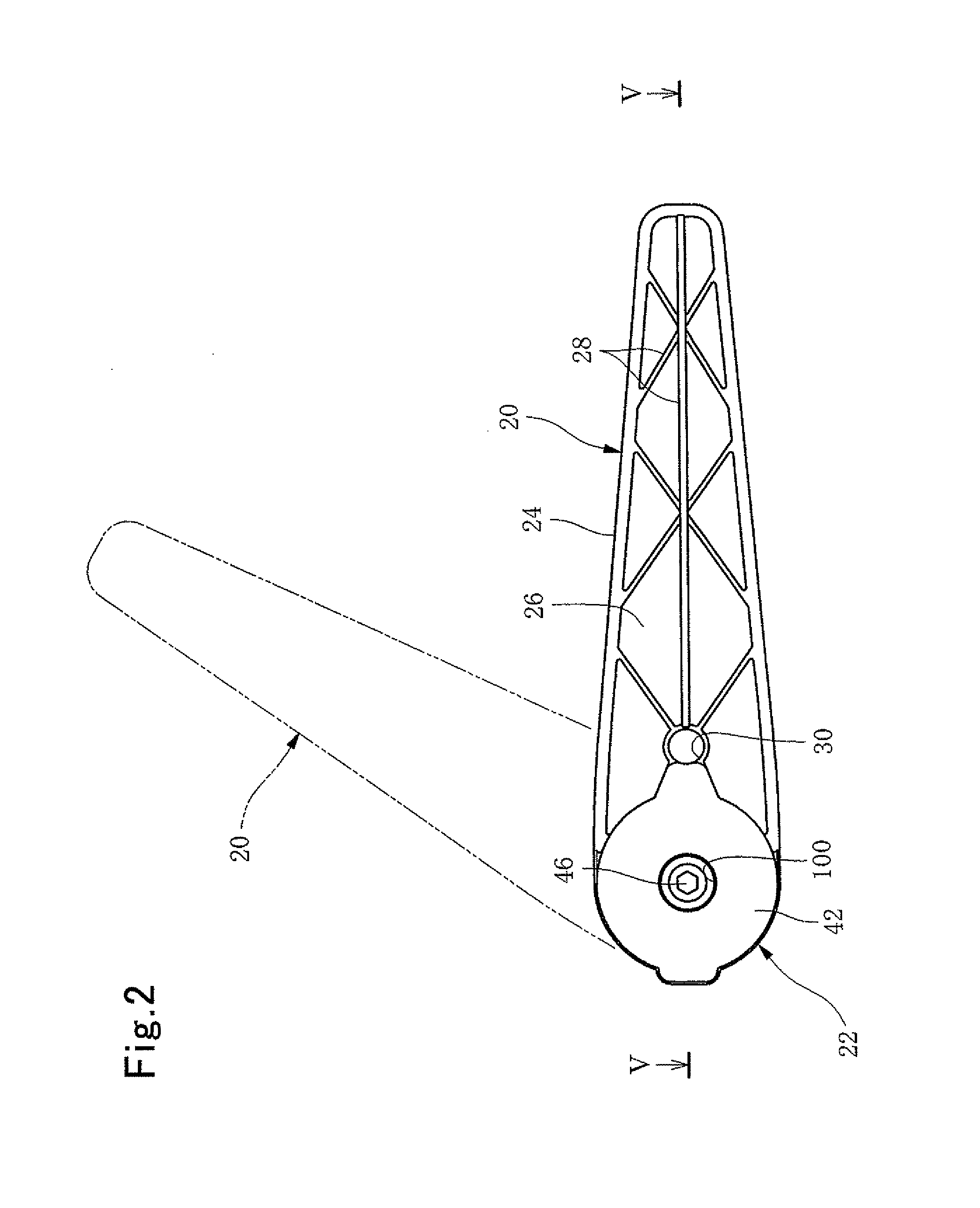
[0141]The armrest device 16 includes an armrest body 20 (see FIG. 2, and FIG. 3) serving as a core, a reinforcement member that is buried inside the armrest 18, a not-shown elastic material covering the armrest body 20 from the outside, and an angle adjusting device 22 being built into the bas...


PUM


Abstract

An arm-rest device is constituted by including the following: an armrest body to be installed to a seat rotatably upward / downward; a ratchet mechanism including stationary-side first ratchet teeth, and movable-side second ratchet teeth rotating integrally with the armrest body; coiled springs for urging those in such a direction that they press one another; releasing cam units for releasing the ratchet mechanism from the meshing; elastic claws and a flanged portion for retaining that release; cut-offs for returning the ratchet mechanism to the meshing. And, the armrest body is made of resin, thereby integrally molding the second ratchet teeth at the time of its molding. It thus becomes an armrest device that is lightweight as a whole, whose assembly can also be done with less man-hour requirements, whose feeling of use is also satisfactory, and which is inexpensive and small in size.

Description

TECHNICAL FIELD[0001]This invention relates to an armrest device to be installed to a seat in automobile, and the like; particularly, to an armrest device in which an angular position of the armrest is adjustable in the up / down rotary direction.BACKGROUND ART[0002]It has been often the case that, in an armrest device to be installed to a seat of automobile, and the like, the armrest (or elbow rest) is made rotatable upward / downward so that it does not interfere with a passenger when he or she sits on the seat or stands up therefrom.[0003]Moreover, it has been carried out to make such an armrest adjustable in the angular position in the up / down rotation so as to make the armrest likely to be used in compliance with users' bodily shape, and so forth.[0004]As a mechanism for that, many have been heretofore employing conventionally a type in which a metallic torsional coiled spring is used as a unidirectional locking spring that allows the upward rotation of armrest body but prohibits t...

Claims


Application Information

Patent Timeline
Patent Type & Authority Patents(United States)
IPC IPC(8): A47C7/54B60N2/46B60N2/75
CPCB60N2/4633B60N2/767
Inventor KOBAYASHI, SEIJIMIZUTANI, TAKESHI
Owner TOKAI CHEM IND CO LTD
Why Eureka
Try Eureka