Steering rack boot

a rack boot and steering rack technology, applied in the field of boots, can solve the problems of high man-hour requirements, damage to the conventional steering boot b>100/b>, and large drawbacks of the conventional method, and achieve the effect of preventing undulating deformation and low cos

Active Publication Date: 2008-09-02
TOYODA GOSEI CO LTD
View PDF10 Cites 0 Cited by
  • Summary
  • Abstract
  • Description
  • Claims
  • Application Information

AI Technical Summary

Benefits of technology

[0015]The present invention has been developed in view of the aforementioned problems. It is therefore an object of the present invention to provide a boot, which can be manufactured at low cost and which can inhibit the undulating deformation from occurring, without ever carrying out a heat treatment.
[0034]In accordance with the present invention, the present boot comprises a bellows whose axial rigidity is designed optimally as a whole. Accordingly, the present boot can securely inhibit the undulating deformation from occurring upon the increment of inner pressure. Thus, the present boot can make the heat treatment for inhibiting the undulating deformation obsolete. Moreover, the man-hour requirements for machining a mold for the present boot are reduced. Consequently, the present boot can be manufactured at low cost.

Problems solved by technology

Accordingly, there might possibly arise such a drawback that the conventional steering boot 100 is damaged.
However, the conventional method for inhibiting the undulating deformation of steering boot by means of heat treatment requires post processing, such as annealing for removing the residual internal stress from the resulting steering boot.
Therefore, the conventional method suffers from the drawback that the man-hour requirements are great.
Consequently, the conventional steering boot has suffered from a high manufacturing cost inevitably.
Moreover, when providing the bellows with the peripheral grooves, the conventional steering boot has adversely exhibited a degraded rigidity in the expansion / contraction direction of the bellows.
As a result, there might arise a probability that, upon the expanding deformation, the part of the bellows, which has undergone the undulating deformation, has been likely to interfere with a clamp, which is fastened to an opposite end of steering gear box.
That is, since the parts of the bellows, which make the outer peripheral side of ball joint, are thinned out, the thinned-out parts are likely to be damaged when they happen to be disposed in between ball joint and flying ballast upon colliding with flying ballast.
Accordingly, it is difficult to inhibit the sections of the bellows, which are disposed away from ball joint, from undergoing the undulating deformation.

Method used


Image

  • Steering rack boot
  • Steering rack boot
  • Steering rack boot

Examples


examples

[0056]Hereinafter, the present invention will be described more specifically with reference to examples and a comparative example.

example no.1

Example No. 1

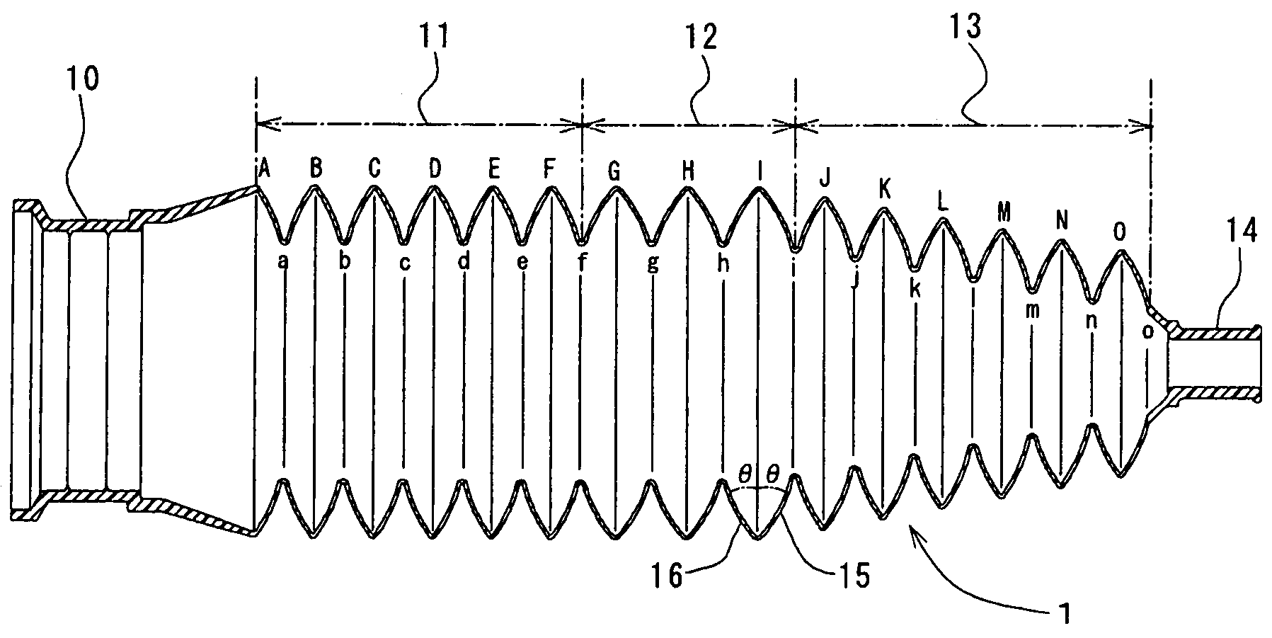
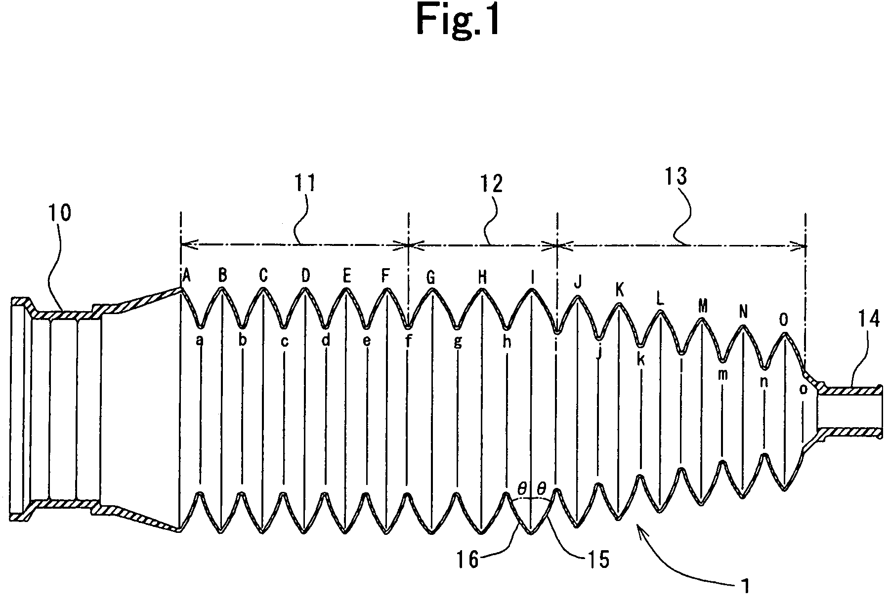
[0057]FIG. 1 illustrates an axial cross-sectional view of a steering boot according to Example No. 1 of the present invention. As illustrated in the drawing, a boot 1 comprises a major-diameter fastener 10, a first bellows 11, a second bellows 12, a minor-diameter-side bellows 13, and a minor-diameter fastener 14. The first bellows 11 is disposed continuously from the major-diameter fastener 10. The second bellows 12 is disposed continuously from the first bellows 11. The minor-diameter-side, bellows 13 is disposed continuously from the second bellows 12. The minor-diameter fastener 14 is disposed continuously from the minor-diameter-side bellows 13. The boot 1 is made from resin, and is manufactured integrally by blow molding. Note that the boot 1 is not subjected to any heat treatment at all.

[0058]The major-diameter fastener 10 and minor-diameter fastener 14 are formed as a ring shape, respectively. Around the major-diameter fastener 10, a not-shown clamp is fitted. T...

example no.2

Example No. 2

[0068]Except that the minor-diameter-side bellows 13 is structured differently, a boot 1 according to Example No. 2 of the present invention is configured in the same manner as the boot 1 according to Example No. 1.

[0069]A boot 1 according to Example No. 2 of the present invention comprises a minor-diameter-side bellows 13 as illustrated in FIG. 4. As shown in the drawing, the minor-side-diameter bellows 13 comprises front membranes 15, and rear membranes 16 in the same manner as that of the boot 1 according to Example No. 1. Similarly, one of the front membranes 15, the section which starts at the top of the crest “M” and finishes at the bottom of the root “m,” for instance, makes an angle θ1 with respect to the diametric direction of the minor-diameter-side bellows 13, and one of the rear membranes 16, the section which starts at the bottom of the root “l” and finishes at the top of the crest “M,” makes an angle θ2 with respect to the diametric direction of the minor-...


PUM


Abstract

A boot includes a major-diameter fastener, a first bellows, a second bellows, a minor-diameter-side bellows, and a minor-diameter fastener. The major-diameter fastener is to be fastened to a mating major-diameter member. The first bellows is disposed continuously from the major-diameter fastener. The second bellows is disposed continuously from the first bellows. The minor-diameter-side bellows is disposed continuously from the second bellows. The minor-diameter fastener is disposed continuously from the minor-diameter-side bellows, and is to be fastened to a mating minor-diameter member. The first bellows exhibits an averaged first axial rigidity. The second bellows exhibits an averaged second axial rigidity. The minor-diameter-side bellows exhibits an averaged third axial rigidity. The averaged first axial rigidity and the averaged third axial rigidity are lower than the averaged second axial rigidity.

Description

BACKGROUND OF THE INVENTION[0001]1. Field of the Invention[0002]The present invention relates to a boot, which is installed to rack-and-pinion type steering apparatus.[0003]2. Description of the Related Art[0004]A steering boot covers a ball joint, which is disposed between a steering gear box and a tie rod. Specifically, one of the opposite ends of the steering boot is fastened to a steering-gear-box end, and the other one of the opposite ends of the steering boot is fastened to a tie-rod end. Moreover, the steering boot is disposed in proximity to engine. Accordingly, the ambient temperature around the steering boot is a high temperature relatively. Consequently, air, which is sealed inside the steering boot, expands to deform the steering boot.[0005]FIG. 9 illustrates a side view of a conventional steering boot, which has deformed. As illustrated in the drawing, when the air inside a conventional steering boot 100 expands so that the conventional steering boot 100 expands and the...

Claims


Application Information

Patent Timeline
Patent Type & Authority Patents(United States)
IPC IPC(8): F16J3/00F16J15/52
CPCF16J3/041
Inventor INAGAKI, HIDEHIKOOTA, KATSUHISA
Owner TOYODA GOSEI CO LTD
Why Eureka
Try Eureka