Display device
a display device and display technology, applied in non-linear optics, instruments, optics, etc., can solve the problems of difficult to control the distance between the counter electrodes, difficult to alternately time-control the application of a coloring voltage, and inability to display stablely and easily achieve a chromatic display
- Summary
- Abstract
- Description
- Claims
- Application Information
AI Technical Summary
Benefits of technology
Problems solved by technology
Method used
Image
Examples
first embodiment
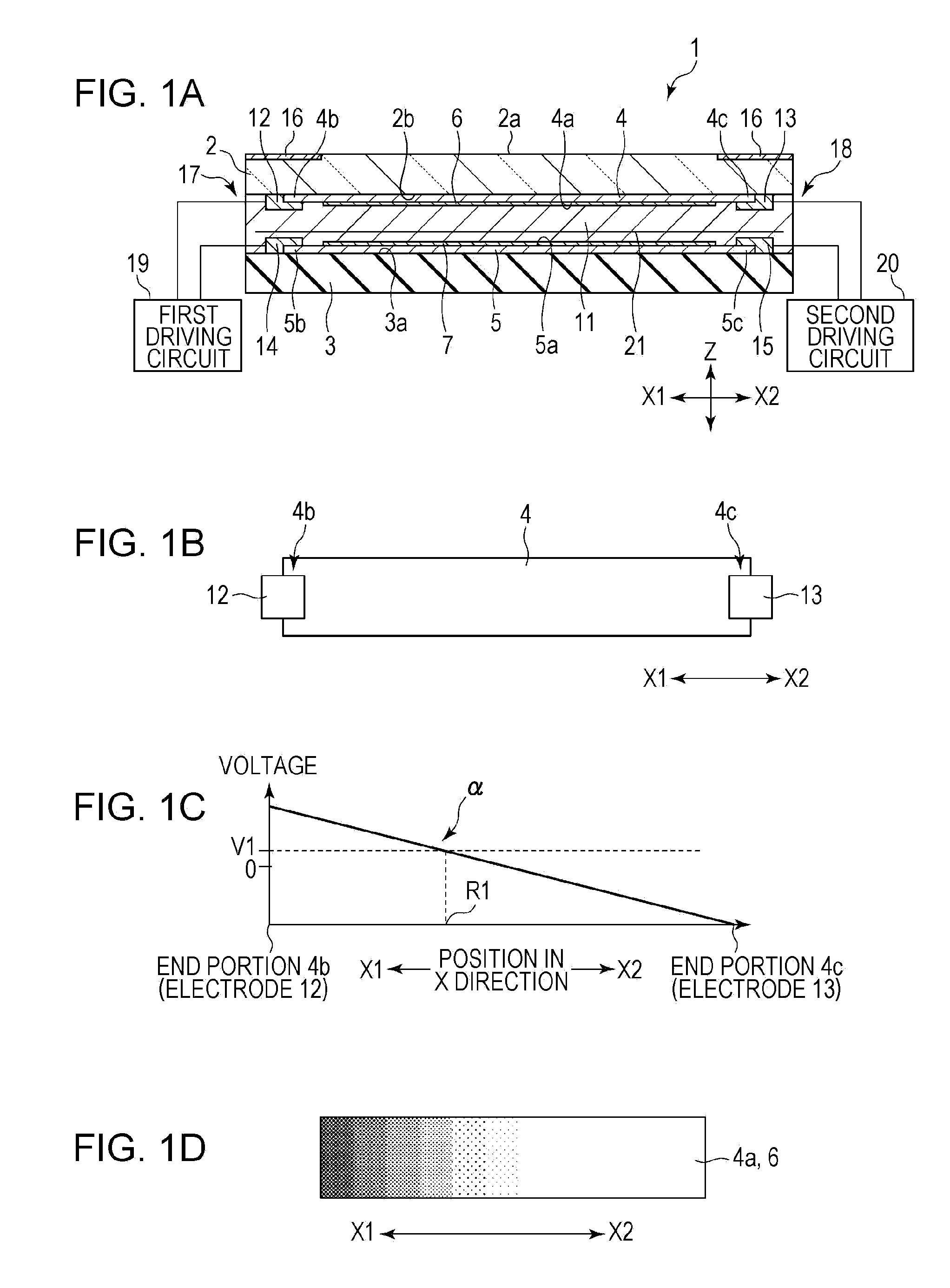
[0025]FIG. 1A is a partial longitudinal sectional view of a display device according to the present invention. FIG. 1B is a plan view of a first resistive layer and first electrodes shown in FIG. 1A. FIG. 1C is a schematic view of a distribution of voltage applied to the first resistive layer. FIG. 1D is a schematic view of a gradation display viewed from a display surface.
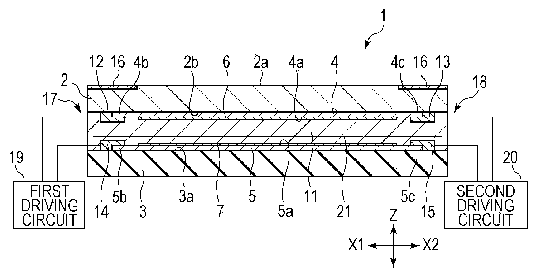
[0026]As shown in FIG. 1A, a first insulating substrate 2 and a second insulating substrate 3 constituting a display device 1 face each other with a space therebetween in the height (Z) direction.
[0027]The outer surface of the first insulating substrate 2 is a display surface 2a. As shown in FIG. 1A, the entire outer surface of the first insulating substrate 2 is not necessarily the display surface 2a. For example, a decorative layer 16 may be formed on the periphery of the display surface 2a. Consequently, a portion of the display surface 2a becomes translucent and a portion of the decorative layer 16 becomes opa...
second embodiment
[0066]FIG. 4 is a partial longitudinal sectional view of a display device according to the present invention. Hereinafter, in FIG. 4, the same components as those in FIG. 1A are denoted by the same reference numerals as those in FIG. 1A.
[0067]In a display device 50 shown in FIG. 4, unlike the display device 1 shown in FIG. 1A, the second resistive layer 5, the second electrochromic layer 7, and the second electrodes 14 and 15 are not disposed on the inner surface 3a of the second insulating substrate 3.
[0068]On the other hand, the configuration of the first resistive layer 4, the first electrochromic layer 6, and the first electrodes 12 and 13 disposed on the inner surface 2b of the first insulating substrate 2 is the same as that shown in FIG. 1A.
[0069]In the display device 50 shown in FIG. 4, unlike the display device 1 shown in FIG. 1A, a driving circuit 51 is connected between the first electrode 12 and the first electrode 13. A voltage is applied between the first electrodes 12...
PUM
| Property | Measurement | Unit |
|---|---|---|
| transmittance | aaaaa | aaaaa |
| transmittance | aaaaa | aaaaa |
| electrochromic | aaaaa | aaaaa |
Abstract
Description
Claims
Application Information
 - R&D
- Intellectual Property
- Life Sciences
- Materials
- Tech Scout
- Unparalleled Data Quality
- Higher Quality Content
- 60% Fewer Hallucinations
Browse by: Latest US Patents, China's latest patents, Technical Efficacy Thesaurus, Application Domain, Technology Topic, Popular Technical Reports.
© 2025 PatSnap. All rights reserved.Legal|Privacy policy|Modern Slavery Act Transparency Statement|Sitemap|About US| Contact US: help@patsnap.com


