System and apparatus for deflection optics

a technology of optical information and optical processing equipment, applied in the field of optics, can solve the problems of unattractive solutions for some applications, unsuitable systems, large and bulky, etc., and achieve the effect of facilitating the deflection of optical information

Active Publication Date: 2013-07-09
INNOVEGA
View PDF53 Cites 123 Cited by
  • Summary
  • Abstract
  • Description
  • Claims
  • Application Information

AI Technical Summary

Benefits of technology

[0008]Depending on the embodiment, the optical path optics may comprise a reflective element, a refractive element, a diffractive element, or a combination thereof. In some embodiments, the optical path optics facilitates deflection of the optical information to the human visual system.

Problems solved by technology

Current systems for optical processing of display information provided by a head-mounted display and non-display information provided by objects other than the head-mounted display may have characteristics that make them unattractive solutions for some applications.
Such systems tend to be large and bulky and ill suited for applications where little space is available for processing the display information and the non-display information.
For example, such systems are unattractive solutions for processing display and non-display information in a fighter pilot's helmet where the space for the optical system is limited.

Method used


Image

  • System and apparatus for deflection optics
  • System and apparatus for deflection optics
  • System and apparatus for deflection optics

Examples


Embodiment Construction

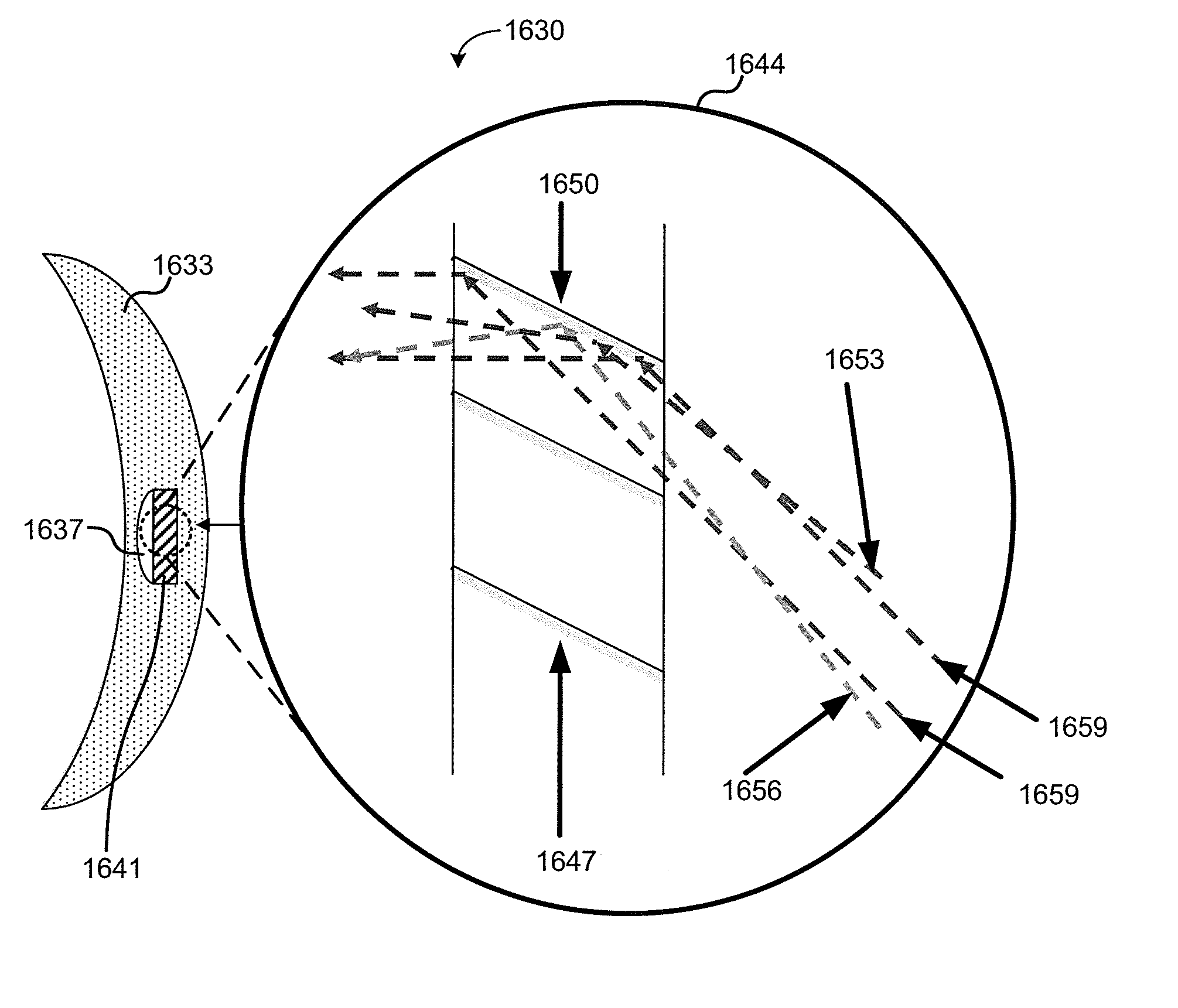
[0004]Various embodiments of the present invention provide systems and apparatuses directed toward using a contact lens and deflection optics to process display information and non-display information.

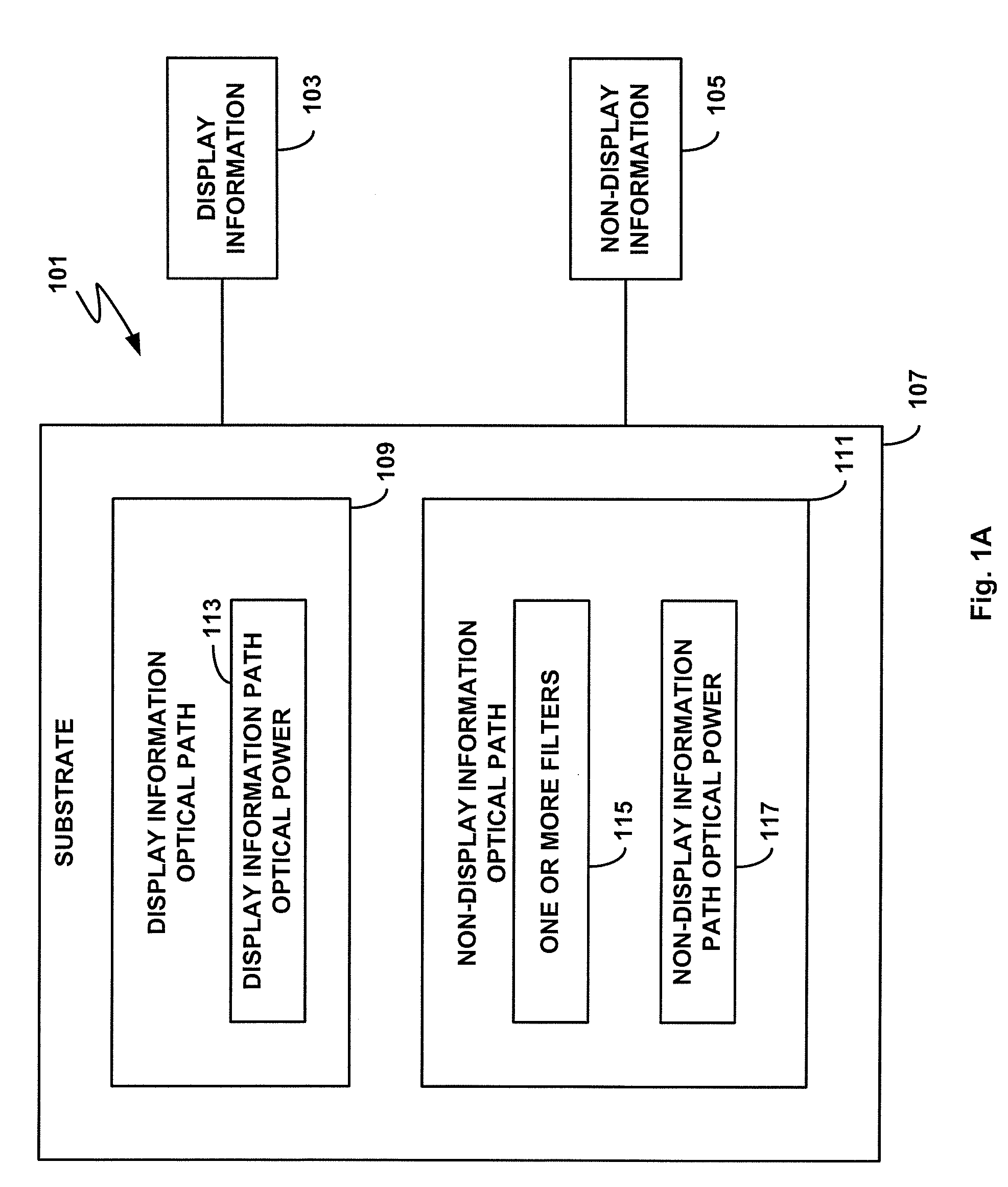
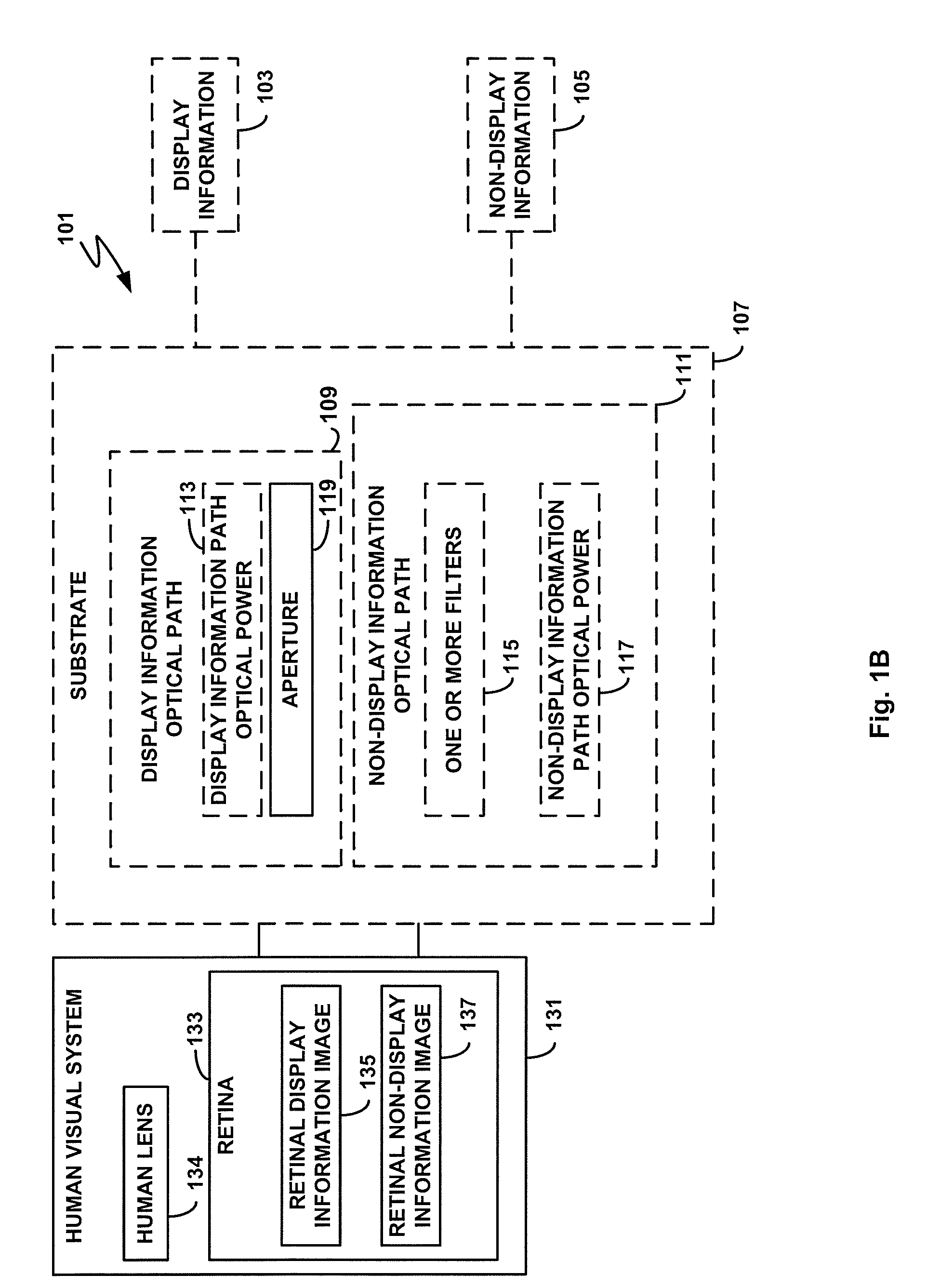
[0005]In one embodiment of the invention, a contact lens assembly is provided, comprising a substrate including optical path optics and configured to receive optical information within an optical path, wherein the optical path optics is configured to be partially deflective such that the optical information is transmitted to the human visual system with deflection.

[0006]In another embodiment of the invention, a contact lens assembly is provided, comprising a substrate including optical path optics and configured to receive display information emitted from a display within a display information optical path, wherein the optical path optics is configured to be partially deflective such that the display information is transmitted to the human visual system with deflection. In additional s...


PUM


Abstract

Various embodiments of the present invention provide for systems and apparatuses directed toward using a contact lens and deflection optics to processes display information and non-display information. In one embodiment of the invention, a contact lens assembly is provided, comprising: a substrate including optical path optics and configured to receive a display information optical path emitted from a display and a non-display information optical path not emitted from the display. The optical path optics of the substrate is configured to be partially deflective such that the non-display information optical path is transmitted to a human visual system without deflection, and the display information optical path is transmitted to the human visual system with deflection.

Description

RELATED APPLICATION[0001]This application is a continuation-in-part of and claims the benefit of U.S. patent application Ser. No. 12 / 204,567 filed Sep. 4, 2008, which is hereby incorporated herein by reference in its entirety.FIELD OF THE INVENTION[0002]The present invention is related to optics and, more specifically, is directed toward optical processing of display information and non-display information using a contact lens and deflection optics.DESCRIPTION OF THE RELATED ART[0003]Current systems for optical processing of display information provided by a head-mounted display and non-display information provided by objects other than the head-mounted display may have characteristics that make them unattractive solutions for some applications. The twin requirements of a large field of view and a comfortable eye-to-system distance for the viewer results in multi-component optical systems where the final optical component has a large diameter. Such systems tend to be large and bulky...

Claims


Application Information

Patent Timeline
Patent Type & Authority Patents(United States)
IPC IPC(8): G02B27/14
CPCG02B27/0172G02C7/04G02C7/101G02C7/102G02B5/23G02B5/30G02B2027/0174
Inventor SPRAGUE, RANDALL
Owner INNOVEGA
Why Eureka
Try Eureka