
Low profile OLED luminaire for grid ceilings

a technology of grid ceilings and luminaires, which is applied in the field of low-profile oled luminaires for grid ceiling systems, can solve the problems of adding to the space requirement, difficult to achieve low-profile luminaire heights, etc., and achieves the effect of low profile, reduced material requirements, and low profil

Active Publication Date: 2013-07-16
ABL IP HLDG
View PDF17 Cites 38 Cited by
  • Summary
  • Abstract
  • Description
  • Claims
  • Application Information

AI Technical Summary

Benefits of technology

The invention is a low profile luminaire that is perfect for use in grid ceiling systems. It is designed to be very thin and lightweight, with a maximum height of only two inches. This makes it easy to install without the need for tie wires. The luminaire is made up of a thin light source and support structure, which is supported by the T-bars of the grid ceiling system. The light source is made of organic light emitting diodes (OLEDs), which are thin and flexible. The invention's low profile and light weight make it a cost-effective and eco-friendly solution for lighting buildings.

Problems solved by technology

Generally, troffer heights less than about 1½ inch would be difficult to achieve.
Use of conventional troffers, which have a depth that causes the troffers to protrude significantly above the grid ceiling, adds to this space requirement.

Method used


Image

  • Low profile OLED luminaire for grid ceilings
  • Low profile OLED luminaire for grid ceilings
  • Low profile OLED luminaire for grid ceilings

Examples


Embodiment Construction

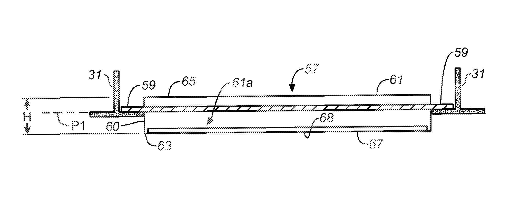
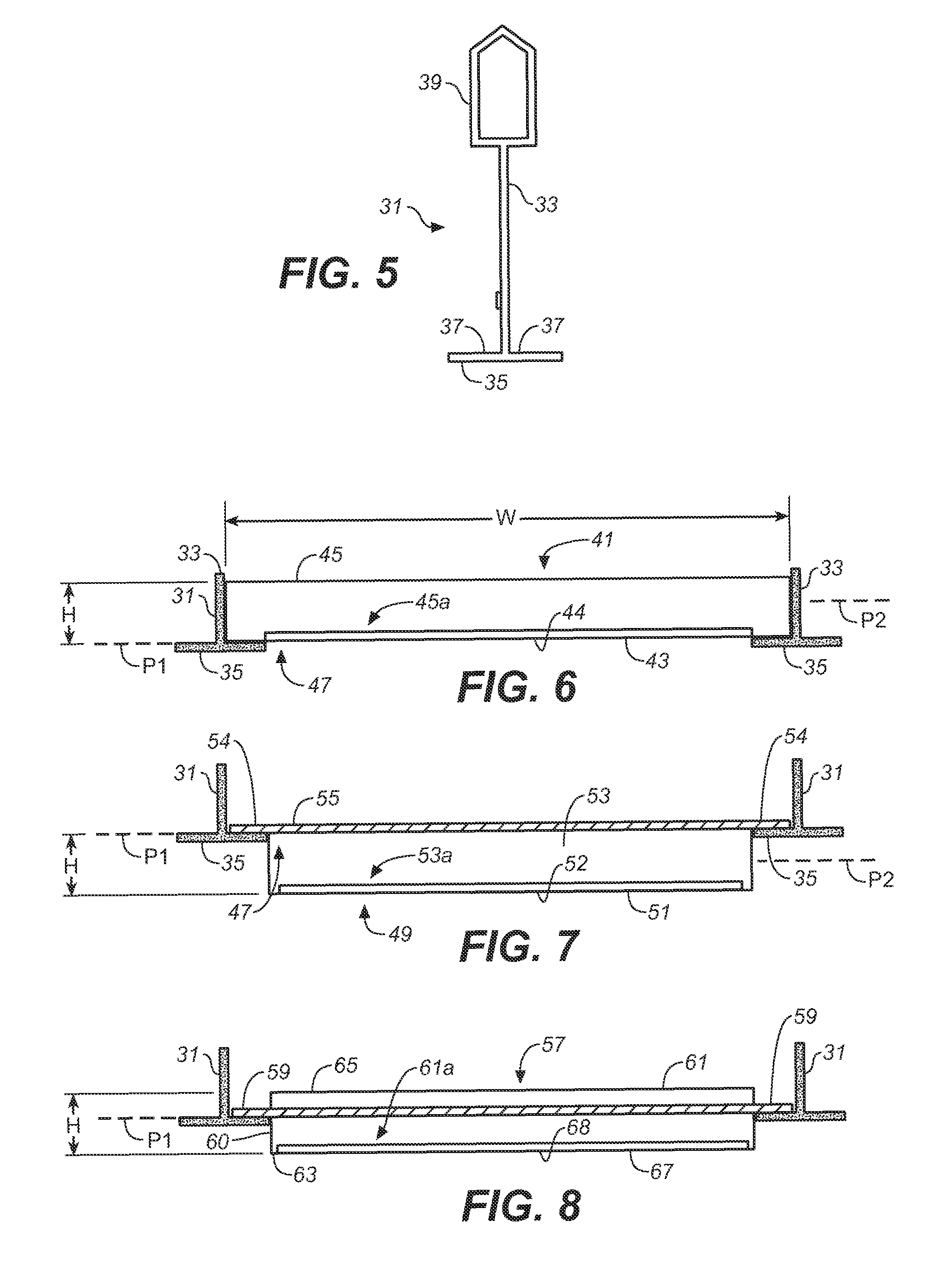
[0048]It is first noted that the luminaires depicted in the accompanying drawings are not necessarily to scale and appear as having a height (denoted by the letter “H”) relative to their perimeter dimensions that are larger than would be the case in the physical implementation of the luminaire.

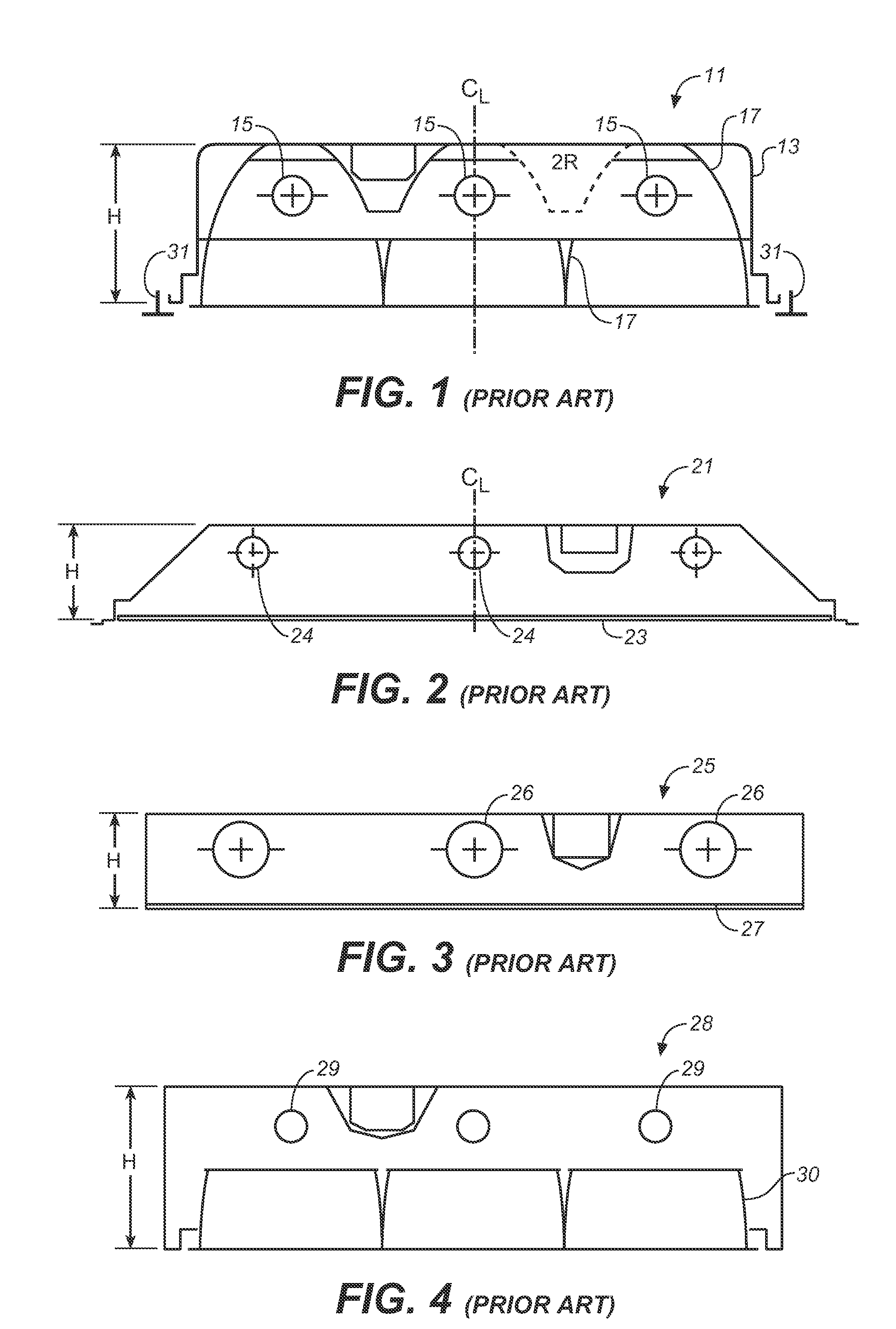
[0049]Referring to the drawings, FIGS. 1-4 graphically illustrate different types of conventional luminaires used with grid ceiling systems. FIG. 1 shows a luminaire in the form of a conventional recessed, parabolic troffer 11, which includes a housing 13 having sufficient height H to accommodate the troffer's fluorescent lamps 15 and surrounding parabolic reflectors 17. FIG. 2 shows another conventional recessed troffer used for grid ceiling systems. In this case, the recessed troffer is a lensed troffer 21, having a lens cover 23 which covers the troffer's fluorescent lamps 24. FIGS. 3 and 4 graphically illustrate surface-mounted troffers. FIG. 3 shows a surface-mounted lensed troffer 25 hav...


PUM


Abstract

A low-profile luminaire has a planar light source comprised of one or more planar organic light emitting diodes (OLEDs). The OLED light source is supported by a low-profile OLED support structure that lies in a plane. The support structure has a maximum height (H) of about two inches and preferably a height of about one inch or less. It also has perimeter dimensions that allow the luminaire to fit within and to be supported by the T-bar grid of a grid ceiling system. Electrical components for driving and controlling the OLED light source can be provided within the support structure or externally of this structure.

Description

CROSS-REFERENCE TO RELATED APPLICATIONS[0001]This application claims the benefit of U.S. provisional patent application No. 61 / 175,767, filed May 5, 2009, which is incorporated herein by reference.BACKGROUND OF THE INVENTION[0002]The present invention generally relates to luminaires, and more particularly to luminaires used with grid ceiling systems.[0003]Grid ceiling systems are commonly used in commercial buildings, schools, and other interior structures. Such ceiling systems are created by suspending a T-bar grid from the building's structural ceiling and filling the T-bar grid with ceiling tiles. The T-bar grid is made up of interconnected T-bars that form grid openings for the ceiling tiles, which, when dropped into the grid openings, are supported on the T-bars' bottom horizontal T-walls. The most common dimensions for the grid openings are the two foot by two foot and four foot by four foot for supporting similarly sized ceiling tiles, however, other grid opening dimensions a...

Claims


Application Information

Patent Timeline
Patent Type & Authority Patents(United States)
IPC IPC(8): F21V33/00
CPCE04B9/00E04B9/0428E04B9/0435E04B9/0464E04B9/0471E04B9/0478E04B9/32F21S8/026F21S8/04E04B9/241F21Y2105/008F21V23/02F21V33/006F21Y2105/00F21Y2115/15
Inventor NGAI, PETER Y. Y.
Owner ABL IP HLDG
Learn More