Needle catheter with an angled distal tip lumen

a needle catheter and distal tip technology, applied in the field of medical devices, can solve the problems of difficult to accurately place and maintain the distal end of the device at the desired treatment site, and provide a catheter, so as to improve the stabilization of the needle catheter, prevent or improve the retention time of the agen

Active Publication Date: 2013-07-16
ABBOTT CARDIOVASCULAR
View PDF35 Cites 18 Cited by
  • Summary
  • Abstract
  • Description
  • Claims
  • Application Information

AI Technical Summary

Benefits of technology

[0004]The invention is directed to a needle catheter configured for injecting an agent into a wall of a patient's body cavity, which directs a needle from the distal tip of the catheter into the wall of the body cavity at an angle relative to the axis of the shaft. The resulting angled injection pathway improves the retention of the agent in the body cavity wall, while keeping a distal section of the catheter substantially perpendicular to the body cavity wall for optimal push against the tissue at the injection site.
[0007]The angled injection pathway in the tissue, which results from the angled distal portion of the catheter needle-through lumen, preferably improves agent retention time. For example, compared to a needle extended straight into the heart tissue (i.e., in a direction normal to the surface of the tissue), the angled injection pathway preferably prevents or reduces the tendency of agent injected into the heart tissue to be expelled from injection pathway. Additionally, the angle preferably provides improved stabilization of the needle catheter which facilitates keeping the distal end face pushed against the beating heart wall during extension of the needle and infusion of the agent into the wall. Moreover, the catheter of the invention is configured to have excellent maneuverability and pushability (transmission of push force from the proximal end of the shaft) for positioning the distal end of the catheter at a desired injection site. These and other advantages of the invention will become more apparent from the following Detailed Description and accompanying exemplary drawings.

Problems solved by technology

However, the beating heart can make it difficult to accurately place and maintain the operative distal end of the device at the desired treatment site.
As a result, one difficulty has been providing a catheter that accurately delivers the agent to the desired site in a patient's heart chamber.

Method used


Image

  • Needle catheter with an angled distal tip lumen
  • Needle catheter with an angled distal tip lumen
  • Needle catheter with an angled distal tip lumen

Examples


Embodiment Construction

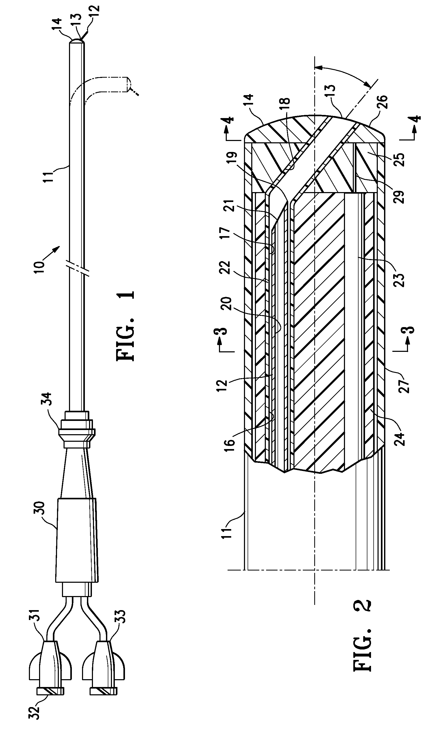
[0013]FIG. 1 illustrates an elevational view of an agent delivery needle catheter 10 embodying features of the invention, generally comprising an elongated catheter shaft 11 having a proximal end and a distal end, and a needle 12 which is slidably disposed in the shaft and which has a retracted configuration, and an extended configuration in which the needle extends from a needle-through port 13 in a distal end face 14 of the catheter. In a presently preferred embodiment, the catheter 10 is configured for reversibly deflecting a distal shaft section, and FIG. 1 illustrates the catheter shaft 11 in a relaxed configuration for introducing and advancing within a patient's vasculature, and illustrates the deflected distal section of the catheter 10 in broken line. The needle 12 is illustrated extended from the catheter shaft in FIG. 1, although is should be understood that the needle is retracted into the shaft during introduction and positioning of the catheter 10 in the patient's anat...


PUM


Abstract

A needle catheter configured for injecting an agent into a wall of a patient's body cavity, which directs a needle from the distal tip of the catheter into the wall of the body cavity at an angle relative to the axis of the shaft. The resulting angled injection pathway improves the retention of the agent in the body cavity wall, while keeping a distal section of the catheter substantially perpendicular to the body cavity wall for optimal push against the tissue at the injection site.

Description

CROSS-REFERENCES TO RELATED APPLICATIONS[0001]None.BACKGROUND OF THE INVENTION[0002]The invention relates generally to the field of medical devices, and more particularly to a catheter used to deliver an agent to a patient's anatomy for the treatment or diagnosis of heart disease.[0003]In the treatment of heart disease, a number of methods have been proposed in which a catheter or other therapeutic device is inserted into a chamber of the heart, and an operative distal end component of the device is used to perform the procedure on the inner wall of the heart. For example, agent delivery catheters, typically having deflectable distal sections, are configured for advancing in the patient's vasculature and into the heart chamber, and an agent delivered directly into the heart wall by jetting or needle-injecting it from the distal tip of the catheter. However, the beating heart can make it difficult to accurately place and maintain the operative distal end of the device at the desired ...

Claims


Application Information

Patent Timeline
Patent Type & Authority Patents(United States)
IPC IPC(8): A61M5/178
CPCA61M25/0068A61M25/0074A61M25/0084A61M2025/009A61M2025/0081
Inventor LUDWIG, FLORIAN N.BASU, SHUBHAYU
Owner ABBOTT CARDIOVASCULAR
Why Eureka
Try Eureka