Bone anchoring device

a technology of bone structure and anchoring device, which is applied in the field of bone anchoring device, can solve the problems of time-consuming and force-intensive process, and high pressure forces acting on the bone structure itsel

Active Publication Date: 2013-07-16
BIEDERMANN TECH GMBH & CO KG
View PDF22 Cites 16 Cited by
  • Summary
  • Abstract
  • Description
  • Claims
  • Application Information

AI Technical Summary

Benefits of technology

[0008]Due to the portion having a bone thread, the bone anchoring device provides the familiar screw feeling and anchoring assurance to the surgeon.
[0009]The bone anchoring device resists against pull-out and rotational forces compared to the known push and turn anchor, especially with weak bone substance. It provides a low insertion force and a high restraining force. In addition, it provides a low torque insertion and removal of the anchoring device.
[0010]With the anchoring device according to the invention the time for the insertion procedure and possible removal procedure is improved due to the push and turn insertion and, if required, a safe removal later on.

Problems solved by technology

The bone screw is manually inserted into the bone by means of a screw driver, which is a time-consuming and force-requiring process.
Moreover, during the process in which the screw is inserted into the bone, high pressure forces may be acting on the bone structure itself, which is undesirable in certain clinical applications such as e.g., in neuro surgery, spinal surgery, pediatric surgery or trauma surgery.

Method used


Image

  • Bone anchoring device
  • Bone anchoring device
  • Bone anchoring device

Examples


first embodiment

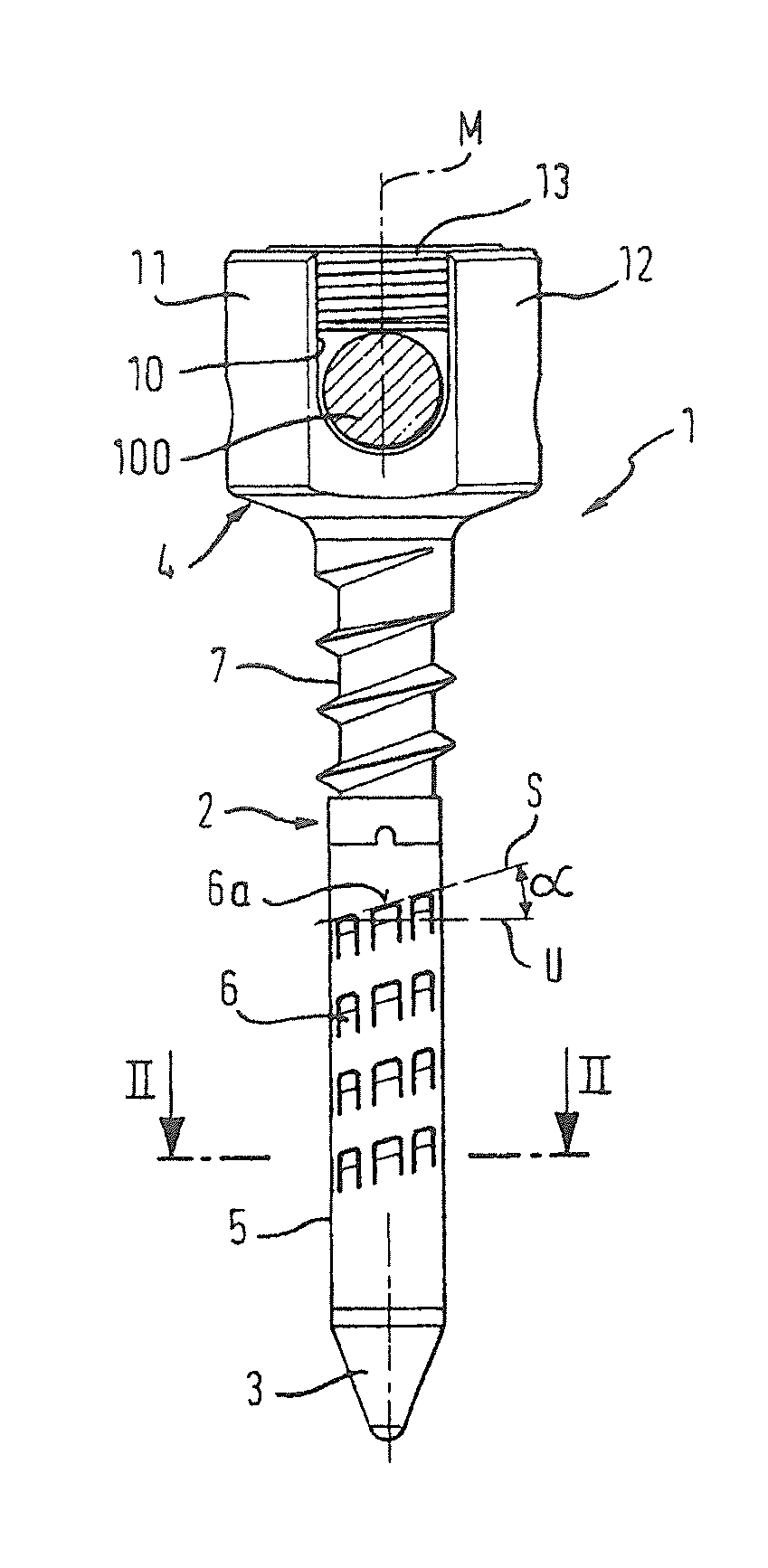
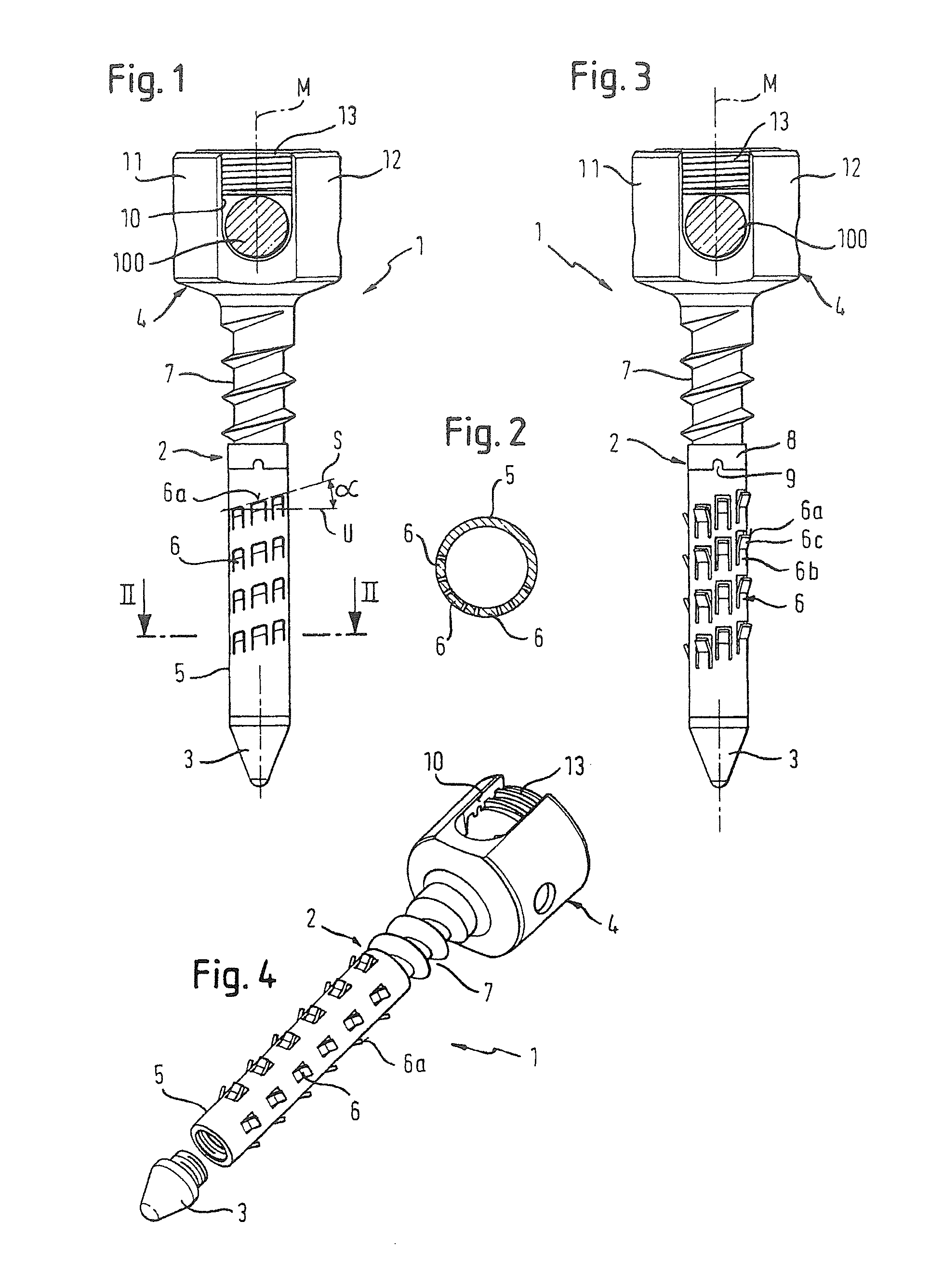
[0026]A bone anchoring device according to the invention is described with reference to FIGS. 1 to 4. The bone anchoring device 1 comprises a shaft 2 with a tip 3 at one end and a head 4 at the other end. The shaft 2 comprises a first section 5 with a plurality of barb elements 6 and a second section 7 comprising a bone thread. The first section 5 is located between the second section 7 and the tip 3. The second section 7 which has the bone thread is located adjacent to or in the vicinity of the head 4 of the anchoring device.

[0027]The first section 5 is preferably formed as a tubular body, as shown in FIG. 4. The barb elements 6 are formed by substantially quadrangular cuts made in the wall of the tubular body, wherein the end base of each barb element 6 is not cut out from the tubular body and acts as the attachment and a bending side for the barb elements 6 in the wall of the tubular body. The arrangement of the barb elements 6 is such that the free ends 6a of the barb elements f...

third embodiment

[0053]FIG. 8 shows the bone anchoring device. It differs from the previous embodiments only in that the head 400 is shaped as the head of a conventional bone screw. For example, it has a lens shape, but any other shape of the head can be selected. The head 400 preferably has means (not shown) for engagement with a screwing-in tool, such as for example a hexagon recess. Furthermore, the head 400 can be formed integrally with the shaft 2 or with a part of the shaft. The bone anchoring device according to this embodiment can be used, for example, to fix a plate to the bone.

fourth embodiment

[0054]FIG. 9 shows the bone anchoring device which differs from the previous embodiments mainly in the design of the head portion. The shaft 2 has at the end which is opposite to the tip 3 a coaxial bore 50 with an internal thread 51. The head 401 is formed as a separate part. It has a projection 52 with an external thread so that it can be screwed-in into the bore 50 to connect the head 401 and the shaft 2. However, the connection between the head 401 and the shaft 2 is not limited to a screw connection. It can be any other detachable connection. The barb elements 6 shown in connection with this embodiment are provided on plates which are attached to the shaft body. In this case, the shaft body can be a full cylinder. However, it is also possible that the shaft is formed like that of the previous embodiments.


PUM


Abstract

A bone anchoring device includes a shaft for anchoring in a bone and a head, the shaft including a first section having a plurality of barb elements, the barb elements being elastically deformable relative to the body of the shaft, and a second section including a bone thread for engagement with the bone. The first section is located near the tip of the shaft and allows insertion by pushing whereas the second section provides enhanced resistance against pull-out.

Description

CROSS-REFERENCE TO RELATED APPLICATION(S)[0001]This application is a continuation of allowed U.S. patent application Ser. No. 11 / 646,973, filed Dec. 27, 2006 now U.S. Pat. No. 8,080,044, which claims the benefit of U.S. Provisional Patent Application Ser. No. 60 / 776,609, filed Feb. 23, 2006, and claims priority from European Patent Application 06003733.0, filed Feb. 23, 2006, the entire disclosures of which are incorporated herein by reference.BACKGROUND[0002]The present invention relates to a bone anchoring device. In particular, it relates to a bone anchoring device which comprises a first section with elastically deformable barb elements for push and turn insertion and an additional second section with a bone thread for enhanced retention in the bone. The bone anchoring device can be used for example in the form of a pedicle screw for the application in spinal surgery or in any other type of bone anchor application.[0003]A known form of a bone anchoring element is a conventional ...

Claims


Application Information

Patent Timeline
Patent Type & Authority Patents(United States)
IPC IPC(8): A61B17/04A61B17/86A61F2/08
CPCA61B17/7032A61B17/7037A61B17/8685A61B2017/8655A61B2017/00867A61B17/864A61B17/58A61B17/84A61B17/86
Inventor BIEDERMANN, LUTZMATTHIS, WILFRIEDDINH, MINH Q.CARPENTER, SCOTTBASUDE, RAGHUVEERLOPES, TRACYRUSSELL, SCOTT M.
Owner BIEDERMANN TECH GMBH & CO KG
Why Eureka
Try Eureka