Method and apparatus for prosthetic valve removal

a prosthetic valve and valve body technology, applied in the field of cardiovascular valve removal, can solve the problems of patient outliving the functional lifespan of the piv, complex treatment modalities, and low patient safety, and achieve the effect of facilitating removal and facilitating removal

Inactive Publication Date: 2013-07-16
VALVEXCHANGE
View PDF97 Cites 74 Cited by
  • Summary
  • Abstract
  • Description
  • Claims
  • Application Information

AI Technical Summary

Benefits of technology

[0012]An advantage of the present invention is the provision of apparatus for facilitating removal of a percutaneously implantable valve (PIV) from a heart.
[0013]Another advantage of the present invention is the provision of a valve holding tool, a cutting tool and a valve removal tool for facilitating removal of a percutaneously implantable valve (PIV) from a heart.
[0014]A still further advantage of the present invention is the provision of a method for facilitating removal of a percutaneously implantable valve (PIV) from a heart.
[0015]These and other advantages will become apparent from the following description taken together with the accompanying drawings and the appended claims.

Problems solved by technology

The demographics of patients suffering valvular disease are broad and the treatment modalities for each are complex.
Because of a number of design constraints, PIV's are expected to be less durable and are likely to wear out sooner than conventional, surgically implantable valves.
Although PIVs are intended for the old, sick patients who have a relatively short life expectancy, there may be instances in which the patient outlives the functional lifespan of the PIV.
Depending on the original size of the first PIV, and the degree of calcification and obstruction, restenting with another PIV may not lead to an effective orifice area that is compatible with good cardiac function.
Since the patient likely received the PIV because they were not a candidate for open-heart surgery and implantation of a conventional bioprosthesis, the patient is unlikely to be a candidate for open heart surgery to replace a worn or failed PIV.

Method used


Image

  • Method and apparatus for prosthetic valve removal
  • Method and apparatus for prosthetic valve removal
  • Method and apparatus for prosthetic valve removal

Examples


first embodiment

[0041]Referring now to FIGS. 5, 6A and 6B, there is shown a valve holding tool 40 of the present invention, according to a Holding tool 40 is generally comprised of a first sliding member in the form of an outer tubular body 42, a second sliding member in the form of an inner rod 52, and an articulating joint member 80 that is pivotally connected with tubular body 42 and inner rod 52. Tubular body 42 and inner rod 52 form a stem portion of holding tool 40. Tubular body 42 defines a cylindrical recess dimensioned to receive rod 52 and has an outer surface dimensioned to receive a detachable handle 60. One end of rod 52 is connected with tubular body 42 by articulating joint member 80, while the other end of rod 52 is adapted to receive a detachable handle 70.

[0042]With reference to FIG. 5, detachable handles 60 and 70 facilitate longitudinally movement of rod 52 relative to tubular body 42 for moving articulating joint member 80 between collapsed and expanded positions, as will be d...

second embodiment

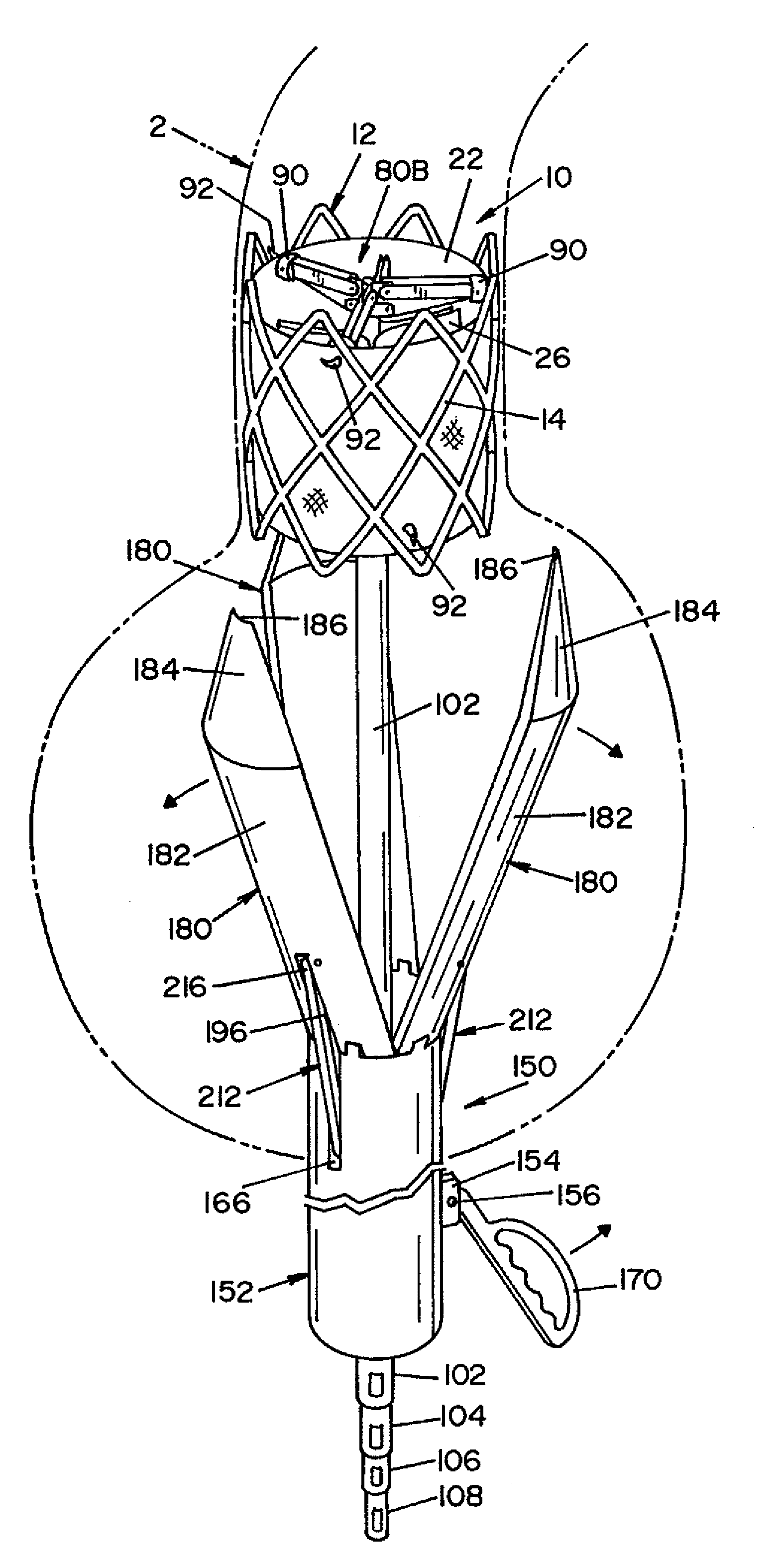
[0048]FIGS. 7 and 8 illustrate a holding tool 40A of the present invention, according to a Holding tool 40A includes a first sliding member in the form of an outer tubular body 102, a second sliding member in the form of an inner tubular body 104, a third sliding member in the form of an inner tubular body 106, a fourth sliding member in the form of an inner rod 108, and a pair of articulating joint members 80A and 80B. In this embodiment, outer tubular body 102, inner tubular body 104, inner tubular body 106, and inner rod 108 form a stem portion of holding tool 40A, wherein inner tubular body 104 extends through outer tubular body 102, inner tubular body 106 extends through inner tubular body 104, and inner rod 108 extends through inner tubular body 106.

[0049]Articulating joint members 80A and 80B are essentially the same as articulating joint member 80 described above. Thus, like components are given the same reference numbers. Articulating joint member 80A is pivotally connecte...


PUM


Abstract

A method and apparatus for facilitating transapical removal of a prosthetic heart valve, i.e., percutaneously implantable valve (PIV), without open-heart surgery. The apparatus includes a holding tool for holding the PIV, a cutting tool for separating the PrV from fibrotic tissue accumulating around the PIV, and a removal tool for extracting the PIV from the heart.

Description

RELATED APPLICATIONS[0001]This application claims the benefit of U.S. Provisional Application No. 60 / 965,602, filed Aug. 21, 2007, which is fully incorporated herein by reference.FIELD OF INVENTION[0002]The present invention relates generally to removal of a previously implanted cardiovascular valve, and more particularly to method and apparatus for facilitating removal of a percutaneously implantable valve (PIV) without open-heart surgery.BACKGROUND OF THE INVENTION[0003]The demographics of patients suffering valvular disease are broad and the treatment modalities for each are complex. Historically, patients younger than 65 years of age have received mechanical valves, while older patients have received bioprosthetic valves. A new demographic of prosthetic valve recipients has emerged recently, namely, the old, sick, inoperable patient who previously would not be a candidate for surgical implantation of a prosthetic valve. These patients are now candidates for a relatively new type...

Claims


Application Information

Patent Timeline
Patent Type & Authority Patents(United States)
IPC IPC(8): A61F2/24A61B17/32
CPCA61F2/2418A61F2/243A61B17/221A61B18/245A61F2/2412A61F2002/9528A61F2230/0054A61B18/22A61B2017/22035A61B2017/22097A61B2018/2272A61B18/1492
Inventor VESELY, IVAN
Owner VALVEXCHANGE
Why Eureka
Try Eureka