
Dual mode charge pump

a charge pump and dual-mode technology, applied in the direction of power conversion systems, instruments, dc-dc conversion, etc., can solve the problems of reducing the flexibility of system applications, large common voltage drift, etc., and achieve the effect of less die area, wide input supply voltage range, and lower cos

Inactive Publication Date: 2013-07-16
RICHTEK TECH
View PDF1 Cites 19 Cited by
  • Summary
  • Abstract
  • Description
  • Claims
  • Application Information

AI Technical Summary

Benefits of technology

The present invention provides a dual mode charge pump that can produce stable positive and negative output voltages with a wider input supply voltage range. It requires fewer power switches, leading to lower costs and a smaller drift in the common voltage. This enables precise control of the output voltage and reduces the impact of load on the voltage.

Problems solved by technology

The input voltage Vbatt is fully limited by the output supply voltages Out+ / Out−, thus reducing flexibility of system applications.
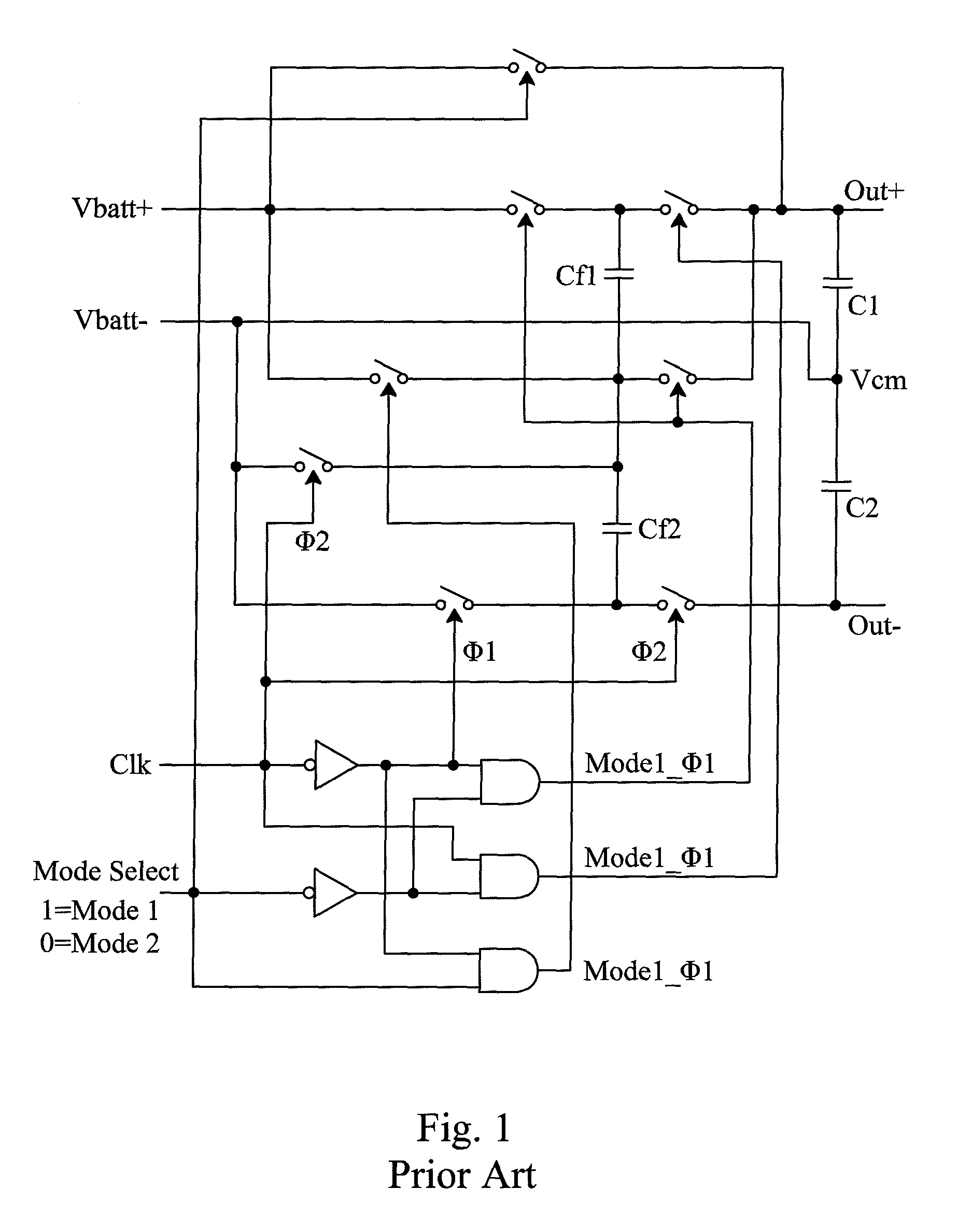
Moreover, in the known dual mode charge pump as disclosed by U.S. Pat. Application Publication No. 2008 / 0044041 and shown in FIG. 1, the common mode voltage Vcm is loosely controlled by the switching actions, resulting in larger common voltage drift, especially when the load currents drawn from the supply voltage output terminals Out+ and Out− are not balanced.

Method used


Image

  • Dual mode charge pump
  • Dual mode charge pump
  • Dual mode charge pump

Examples


Embodiment Construction

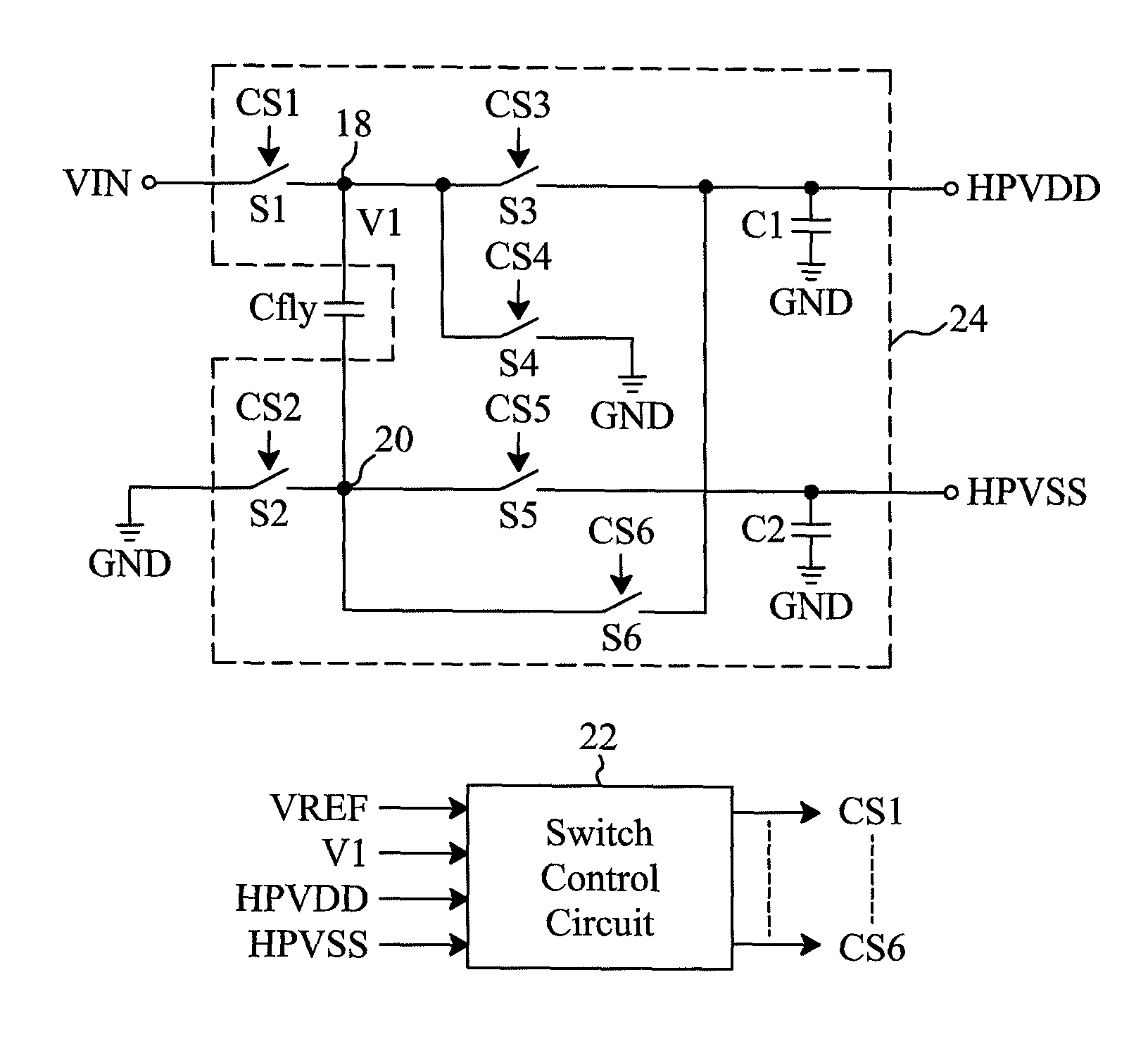
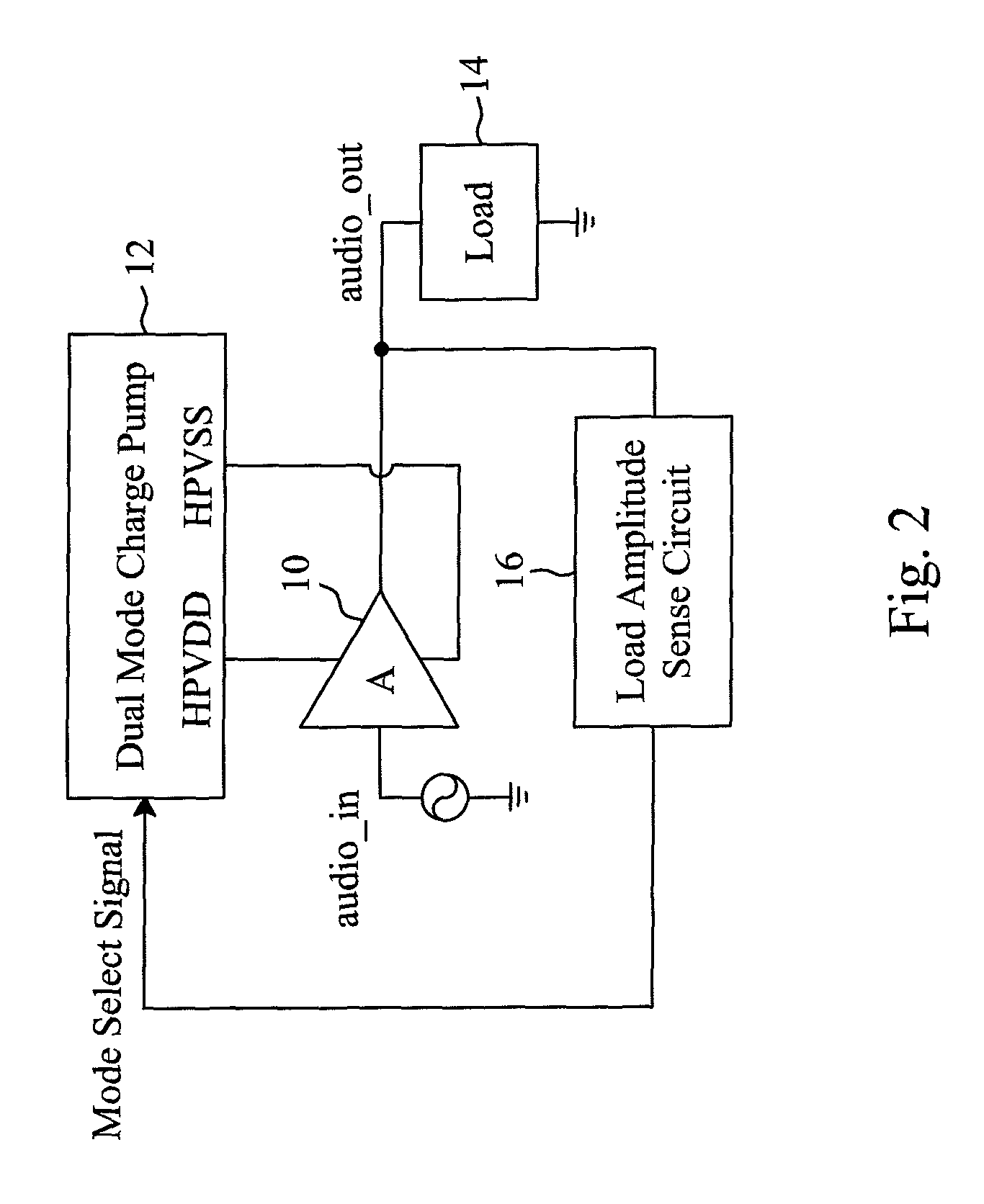
[0024]As shown in FIG. 2, an amplifier system has a Class G or Class H amplifier as its audio output device 10 for amplifying an input signal audio_in to generate an output signal audio_out for a load 14, a dual mode charge pump 12 operating in a first mode or a second mode responsive to a mode select signal to provide multiple sets of supply voltages HPVDD and HPVSS to power input terminals of the audio output device 10, and a load amplitude sense circuit 16 for sensing the amplitude of the output signal audio_out to identify the condition of the load 14 and determining the mode select signal according to the condition of the load 14 to switch the dual mode charge pump 12 between the first and second modes.

[0025]FIG. 3 is a circuit diagram of an embodiment for the dual mode charge pump 12 shown in FIG. 2, which includes a flying capacitor Cfly, a switch control circuit 22 and a switch capacitor network 24. In the switch capacitor network 24, a switch S1 is connected between a power...


PUM


Abstract

A dual mode charge pump is operable in a first mode or a second mode for providing positive and negative output voltages that can be stabilized by adjusting the charging time of two terminals of a flying capacitor or by adjusting the charging / discharging time of the positive and negative voltage output terminals. The dual mode charge pump can apply to a much wider input supply voltage range with less numbers of power switches, thus requiring less die area and lower costs. Moreover, the dual mode charge pump can precisely define a common mode voltage, thus making the common voltage drift smaller and less load dependent, especially when the output supply voltages are under different load conditions.

Description

FIELD OF THE INVENTION[0001]The present invention is related generally to a dual mode charge pump and, more particularly, to a dual mode charge pump for providing positive and negative supply voltages.BACKGROUND OF THE INVENTION[0002]Class H amplifiers are known to improve the efficiency of conventional Class AB amplifiers. Traditional Class G and Class H amplifiers require multiple power supplies for providing positive and negative supply voltages. Recently, combining a voltage generation method to generate a set of positive and negative supply voltages with selectable modes (to generate different bipolar supply voltages) was found to be an efficient and cost effective way to implement Class G or Class H amplifiers.[0003]A power generation method with a dual mode charge pump is first proposed by U.S. Pat. Application Publication No. 2008 / 0044041, which uses two flying capacitors and eight controlled switches. Later, U.S. Pat. No. 7,626,445 proposes an improved dual mode charge pump...

Claims


Application Information

Patent Timeline
Patent Type & Authority Patents(United States)
IPC IPC(8): G05F1/10
CPCH02M3/07H02M2003/071H02M3/071
Inventor WEI, WEI-HSINGUO, JWIN-YENCHANG, TENG-HUNGHSIAO, MING-JUN
Owner RICHTEK TECH
Learn More