Composite magnetic core assembly, magnetic element and fabricating method thereof

a composite magnetic core and magnetic element technology, applied in the field of composite magnetic core assembly, can solve the problems of large overall volume, time-consuming fabrication process, and limited application thereof, and achieve the effects of shortening the manufacturing process, increasing the operating efficiency, and reducing the cost and overall volum

Inactive Publication Date: 2013-07-16
DELTA ELECTRONICS INC
View PDF19 Cites 21 Cited by
  • Summary
  • Abstract
  • Description
  • Claims
  • Application Information

AI Technical Summary

Benefits of technology

[0008]It is an object of the present invention to provide a composite magnetic core assembly, a magnetic element and a fabricating method for increasing operating efficiency, shortening fabricating time and reducing cost and overall volume by connecting alloy powder core and ferrite in series.
[0009]Another object of the present invention provides a composite magnetic core assembly, a magnetic element and a fabricating method for reducing DC resistance, copper loss and near-field radiation.

Problems solved by technology

In such situation, the overall volume is relatively huge.
The process of fabricating an inductor by using the ring-shaped powder core needs a manual winding step, and thus the fabricating process is time-consuming.
In other words, the application thereof is largely restricted.
In a case that the permeability of the magnetic powder core is further reduced, the fringing flux is increased and a near-field radiation problem occurs.
In practice, the magnetic core member with the air gap may incur near-field radiation, electromagnetic interference and high eddy-current loss.
This patent, however, fails to obviate the above drawbacks encountered from the prior art.
This method uses too many components and is very complicated.
As such, the near-field radiation and electromagnetic interference problems are incurred.
From the above discussions, it is found that the conventional magnetic elements fail to effectively increase the operating efficiency, shortening the fabricating time or reducing the cost and overall volume of the magnetic core assembly.

Method used


Image

  • Composite magnetic core assembly, magnetic element and fabricating method thereof
  • Composite magnetic core assembly, magnetic element and fabricating method thereof
  • Composite magnetic core assembly, magnetic element and fabricating method thereof

Examples


example 1

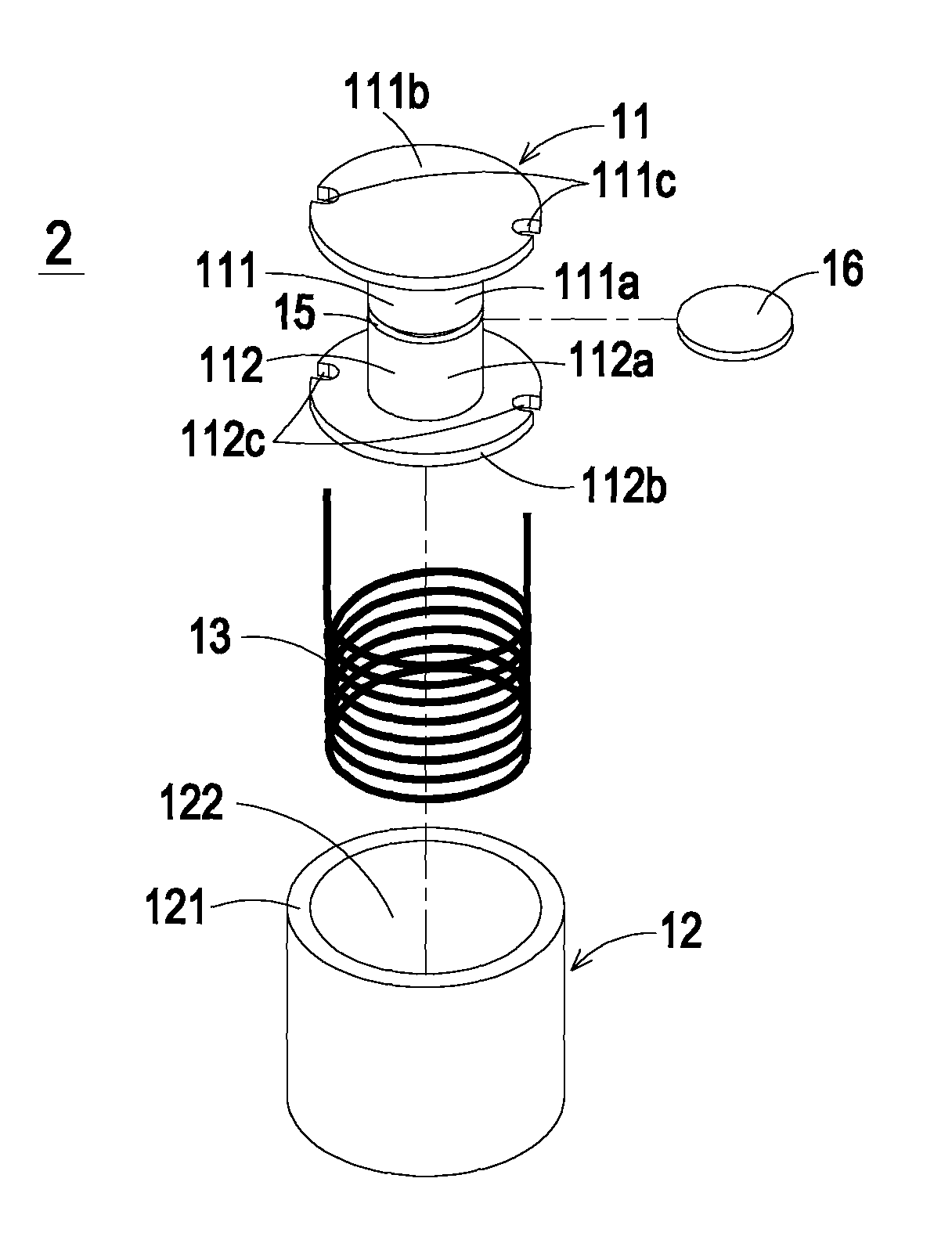
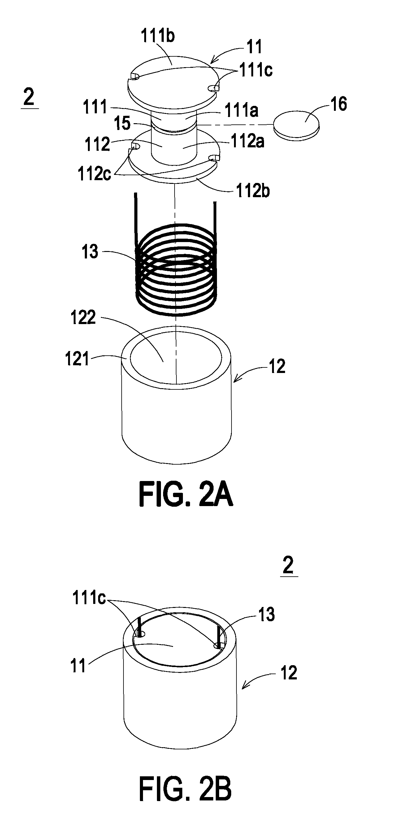
[0050]A conventional ring-shaped magnetic core of an inductor having a dimension of 35.8 mm×22.35 mm×10.46 mm and 70 turns of enamel-insulated wire (Φ1.5 mm) (by a dual-ring winding mechanism) is provided as a comparison sample. The ring-shaped magnetic core is made of FeAlSi powder core, and has an initial permeability value of 60 and a DC resistance of 45.9 nm. An exemplary magnetic element 2 of the present invention is an inductor. The magnetic element 2 has an air gap of about 0.5 mm. The inner magnetic core 11 is made of FeAlSi powder core, and has an initial permeability value of 26. The configurations of the magnetic element 2 are similar to those shown in FIGS. 2A and 2B. A three-layered enamel-insulated wire (Φ1.4 mm) with 48 turns is wound around the first part 111 and the second part 112 of the inner magnetic core 11. Then, the three-layered enamel-insulated wire and the inner magnetic core 11 are collectively accommodated within the receptacle 122 of the outer magnetic c...

example 2

[0051]A conventional ring-shaped magnetic core of an inductor as described in Example 1 is provided as a comparison sample. An exemplary magnetic element 2 of the present invention is an inductor. The magnetic element 2 has an air gap of about 0.5 mm. The inner magnetic core 11 is made of FeAlSi powder core, and has an initial permeability value of 30. The configurations of the magnetic element 2 are similar to those shown in FIGS. 2A and 2B. A four-layered enamel-insulated wire (Φ1.29 mm) with 48 turns is wound around the first part 111 and the second part 112 of the inner magnetic core 11. Then, the four-layered enamel-insulated wire and the inner magnetic core 11 are collectively accommodated within the receptacle 122 of the outer magnetic core 12 (made of ferrite). The resulting inductor has an assembling air gap of about 0.4 mm and a DC resistance of 35.7 nm. The measured inductance under maximum working current is increased by about 7%.

example 3

[0052]A conventional ring-shaped magnetic core of an inductor having a dimension of 27.6 mm×14.1 mm×11.99 mm and 60 turns of enamel-insulated wire (Φ0.8 mm) is provided as a comparison sample. The ring-shaped magnetic core is made of FeAlSi powder core, and has an initial permeability value of 26. Two inductors of the present invention are used to compare the anti-DC bias performance. These two inductors have the same parameters except for the inner magnetic core 11. The inner magnetic core 11 of one inductor is made of FeAlSi μ26 powder core. The inner magnetic core 11 of the other inductor is made of FeAlSi μ125 powder core with an air gap such that the equivalent permeability is equal to 26. FIG. 6 is a plot illustrating the comparison of anti-DC bias performance between these two inductors. The curve “a” indicates the inductor having the FeAlSi μ26 powder core as the inner magnetic core. The curve “b” indicates the inductor having the FeAlSi μ125 powder core (with an air gap) as...


PUM

PropertyMeasurementUnit
DC resistanceaaaaaaaaaa
magneticaaaaaaaaaa
saturation flux densityaaaaaaaaaa

Abstract

A composite magnetic core assembly includes an inner magnetic core and an outer magnetic core. The inner magnetic core is made of a high saturation flux density and low permeability material. The outer magnetic core is made of a low saturation flux density and high permeability material. The outer magnetic core includes a ring-shaped wall and a receptacle. The inner magnetic core is accommodated within the receptacle.

Description

FIELD OF THE INVENTION[0001]The present invention relates to a magnetic core assembly, and more particularly to a composite magnetic core assembly. The present invention also relates to a magnetic element including the composite magnetic core assembly and a fabricating method thereof.BACKGROUND OF THE INVENTION[0002]Magnetic elements such as inductors or transformers are widely used in switch-mode power converters. The magnetic element is a key component influencing power density, efficiency and reliability of the power converter. Conventionally, the magnetic element (e.g. an inductor) used in the switch-mode power converter is made of ferrite, ring-shaped powder core, or the like. Since different magnetic core materials have different hysteresis properties, the losses of different magnetic cores are distinguished. Generally, the magnetic core loss is resulted from alternate magnetic fields within the magnetic core. The magnetic core loss is a function of the operating frequency and...

Claims


Application Information

Patent Timeline
Patent Type & Authority Patents(United States)
IPC IPC(8): H01F27/24H01F17/04
CPCH01F3/10H01F17/04H01F41/0246H01F1/22H01F1/36Y10T29/49073H01F2003/106H01F3/14
Inventor CHU, JIANGCHEN, WEICHENG, I-CHIWU, YI-FANHUANG, ZHI
Owner DELTA ELECTRONICS INC
Why Eureka
Try Eureka