Optical sheet for use as a display surface

Active Publication Date: 2013-07-16
DAI NIPPON PRINTING CO LTD
View PDF18 Cites 2 Cited by
  • Summary
  • Abstract
  • Description
  • Claims
  • Application Information

AI Technical Summary

Benefits of technology

The invention provides an optical sheet that has clear and distinct colors, including vivid complexion and blackness, and image crispness. The sheet also has convenient evaluations of these properties using a new method called Q / U, which allows for more accurate assessment. Overall, this invention improves the quality of optical sheets and enhances the overall performance of the sheets used in optical applications.

Problems solved by technology

However, contrast often differs even with the same haze value, and it has been found that, even with production using the haze value and the ratio of the interior haze and total haze as indexes, for example, it is not always possible to stably produce a satisfactory optical sheet.

Method used


Image

  • Optical sheet for use as a display surface
  • Optical sheet for use as a display surface
  • Optical sheet for use as a display surface

Examples


production example 1

[0191]Triacetylcellulose (80 μm thickness, FujiFilm Corp.) was prepared as a transparent base material.

[0192]The transparent resin used was a mixture of pentaerythritol triacrylate (PETA), dipentaerythritol hexaacrylate (DPHA) and polymethyl methacrylate (PMMA) (weight ratio: PETA / DPHA / PMMA=86 / 5 / 9) (refractive index: 1.51), and polystyrene particles (refractive index: 1.60, mean particle size: 3.5 μm, (d75-d25) / MV=0.05) and styrene-acrylic copolymer particles (refractive index: 1.56, mean particle size: 3.5 μm, (d75-d25) / MV=0.04) were added thereto as translucent particles, at 18.5 and 3.5 parts by weight, respectively, with respect to 100 parts by weight of the transparent resin.

[0193]A resin composition obtained by mixing a mixed solvent of toluene (boiling point: 110° C., relative evaporation rate: 2.0) and cyclohexanone (boiling point: 156° C., relative evaporation rate: 0.32) (weight ratio: 7:3) as the solvent at 190 parts by weight with respect to 100 parts by weight of the tr...

production examples 2-7

and Production Examples 10-19

[0195]An optical sheet was fabricated for Production Example 1, changing the type of transparent base material, the type of transparent resin, the types and content of translucent particles, the type and content of the solvent, the drying conditions and the coating film thickness, as listed in Table 1. The results of evaluating each optical sheet in the same manner as Production Example 1 are shown in Table 2.

production example 8

[0196]Triacetylcellulose (80 μm thickness, FujiFilm Corp.) was prepared as a transparent base material.

[0197]Pentaerythritol triacrylate (PETA, refractive index: 1.51) was used as the transparent resin, and there were added thereto as translucent particles, styrene-acrylic copolymer particles (refractive index: 1.51, mean particle size: 9.0 μm, (d75-d25) / MV=0.04) and polystyrene particles (refractive index: 1.60, mean particle size: 3.5 μm, (d75-d25) / MV=0.05), at 10.0 parts by weight and 16.5 parts by weight, respectively, with respect to 100 parts by weight of the transparent resin.

[0198]A resin composition obtained by mixing a mixed solvent of toluene (boiling point: 110° C., relative evaporation rate: 2.0) and cyclohexanone (boiling point: 156° C., relative evaporation rate: 0.32) (weight ratio: 7:3) as the solvent at 190 parts by weight with respect to 100 parts by weight of the transparent resin, was coated onto the transparent base material and dry air at 85° C. was circulated...


PUM


Abstract

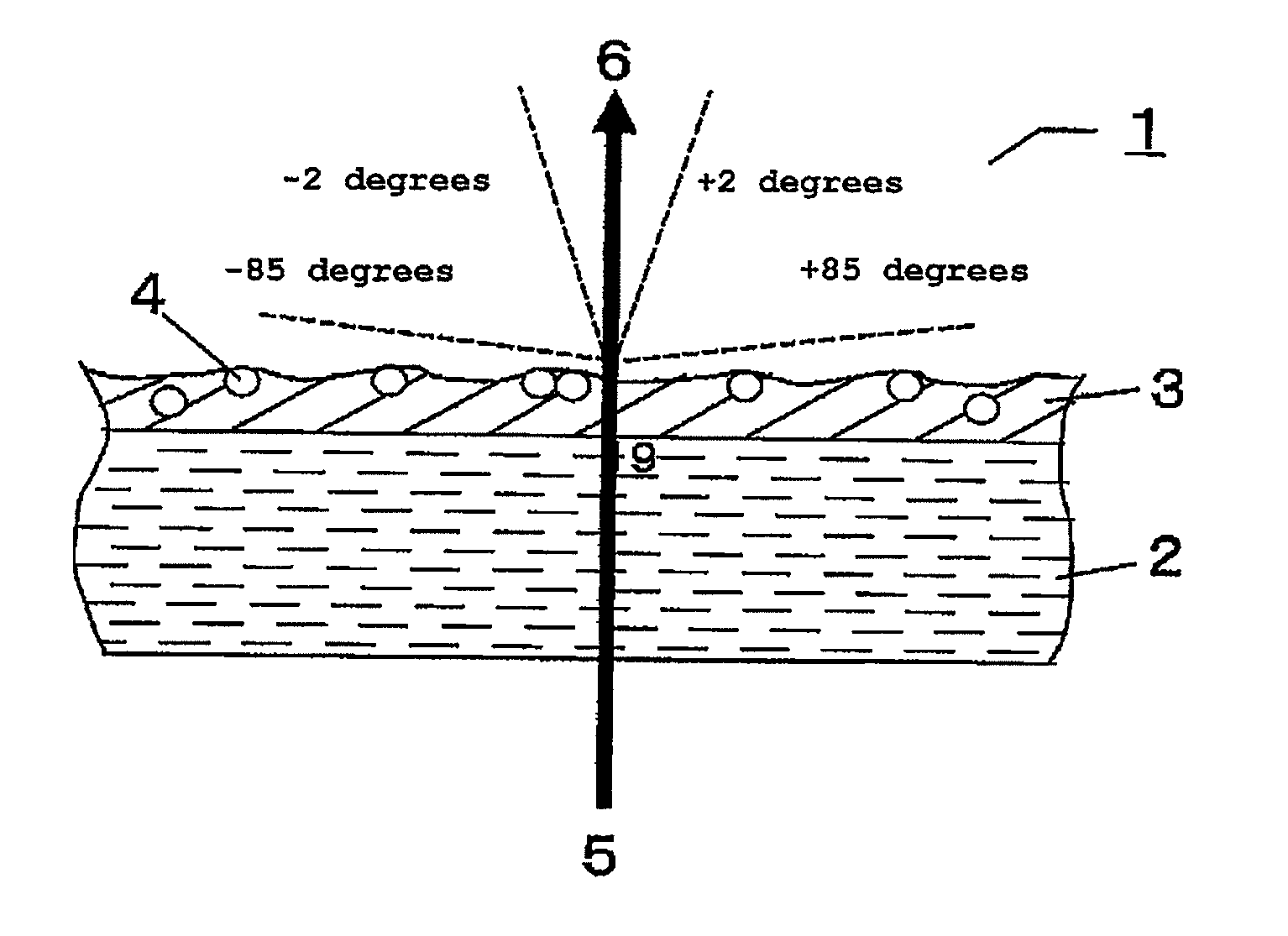
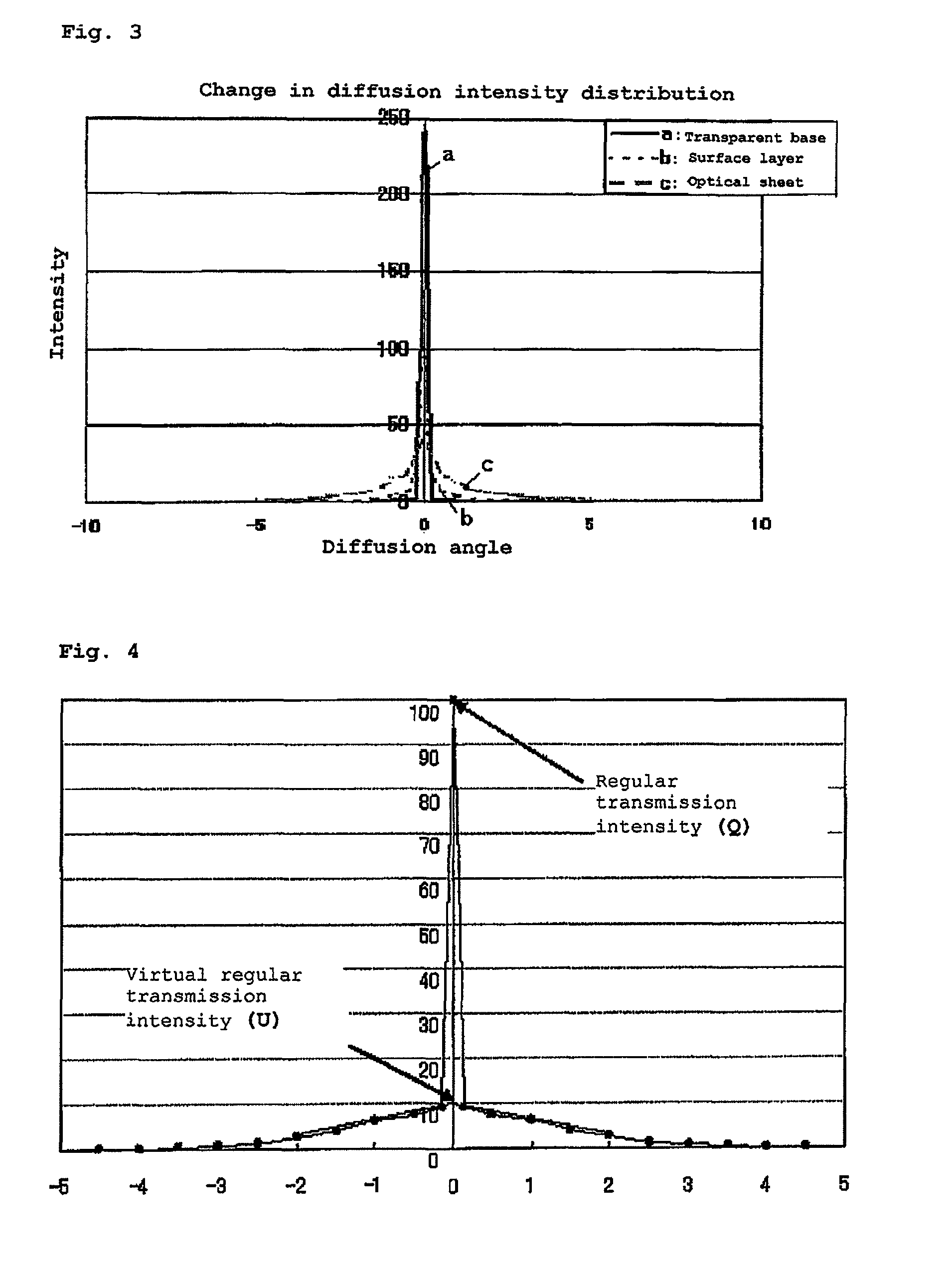
There is provided an optical sheet used as a display device surface as a functional layer on at least one side of a transparent base material. A diffusion factor on the outer surface and / or interior of the functional layer, wherein the relationship represented by the following formula (I) is satisfied. 2.1<Q / U<21.4 (I), where Q (regular transmission intensity) is diffuse transmission intensity at 0 degrees and U (virtual regular transmission intensity is transmission intensity, which is a straight line connecting the transmission intensities at diffusion regular transmission ±2 degrees and diffusion regular transmission ±1 degree, extrapolated from the diffuse regular transmission angle.

Description

TECHNICAL FIELD[0001]The present invention relates to an optical sheet with excellent vivid complexion and blackness and excellent image crispness, that is suitable for combination of dynamic images and still images.BACKGROUND ART[0002]Optical sheets used for display device surfaces have layers with functions such as an anti-glare property, antistatic property and antifouling property laminated as functional layers on the observer side of a transparent base material.[0003]To exhibit these functions, in order to impart an anti-glare property, for example, methods of forming a concavoconvex shape in the surface layer or adding diffusion particles to the resin forming the surface layer are employed. Conductive fine particles or a conductive resin may be added to impart an antistatic property, or a fluorine-containing polymer or stain-proofing agent may be added in order to impart an antifouling property.[0004]Since such diffusion particles, conductive fine particles and additives are n...

Claims


Application Information

Patent Timeline
IPC IPC(8): G02F1/1335
CPCG02B5/0221G02B5/0242G02B5/0278G02B5/0268G02F2201/38G02F1/133528
Inventor KODAMA, TAKASHIFURUI, GENHONDA, MAKOTO
Owner DAI NIPPON PRINTING CO LTD
Why Eureka
Try Eureka