LED light source and image reading apparatus

a technology of led light source and image reading device, which is applied in the direction of lighting and heating apparatus, instruments, optical elements, etc., can solve the problems of limited light guide length, inability to read, and uneven light amount of image as a whole, so as to suppress the height dimension of light guide, thin compact led light source, and suppress light leakage

Inactive Publication Date: 2013-07-16
NISCA KK
View PDF19 Cites 30 Cited by
  • Summary
  • Abstract
  • Description
  • Claims
  • Application Information

AI Technical Summary

Benefits of technology

[0015]More specifically, the curved reflecting surface is formed of an elliptical curved surface, and the end in the main scanning line direction extends to a position equal to the critical angle of the LED light. The LED uses a single chip type of white LED comprised of a blue LED chip and YAG (Yttrium Aluminium Garnet) yellow fluorescent material, two or more white LEDs are arranged along the main scanning line direction, and both disposed out of the critical angle region, and by causing total reflection of the light from each white LED by the light guide, light leaking from the light guide is suppressed. Further, in the light guide, the outside surface including the curved reflecting surface except the lighting region is surrounded with a support frame that is a white reflecting body to suppress light leaking from the light guide.
[0024]Further, when the light guide is formed by resin molding, it is not necessary to vary the diameter of the light guide, the light guide does not become deformed by distortion, etc. due to flow and ambient temperature, and productivity of the LED light source is excellent.

Problems solved by technology

First, the above-mentioned optical reduction type image reading apparatus has the following problem.
As a result, the center portion is bright, the opposite sides are dark, and unevenness develops in the light amount of the image as a whole.
However, this method of providing the slit plate SH is to reduce the entire light-amount level by cutting the amount of received light of the light-receiving means CCD, the whole of the image to read is darkened, and reading is sometimes made impossible due to a lack of the light amount.
Meanwhile, the following problem arises in the above-mentioned LED light source LA.
However, in the method of gradually decreasing the diameter of the light guide so that the surface with the reflecting surface bodies RG1 formed is a slant α, there are limitations in the length of the light guide, and it is hard to prepare a light guide RG with a uniform light-source region.
Further, when the light guide RG is formed by resin molding, the light guide becomes deformed by distortion, etc. due to flow and ambient temperature by varying the diameter of the light guide, and the deformation tends to be a factor of unevenness in the light amount.

Method used


Image

  • LED light source and image reading apparatus
  • LED light source and image reading apparatus
  • LED light source and image reading apparatus

Examples


embodiment 2

[Embodiment 2]

[0060]Embodiment 2 will be described below based on FIGS. 14 and 15. In Embodiment 2, the LED light source of the invention described previously is used as a light source of a contact image sensor type image reading apparatus.

[Configuration and Operation Outline of the Image Reading Apparatus]

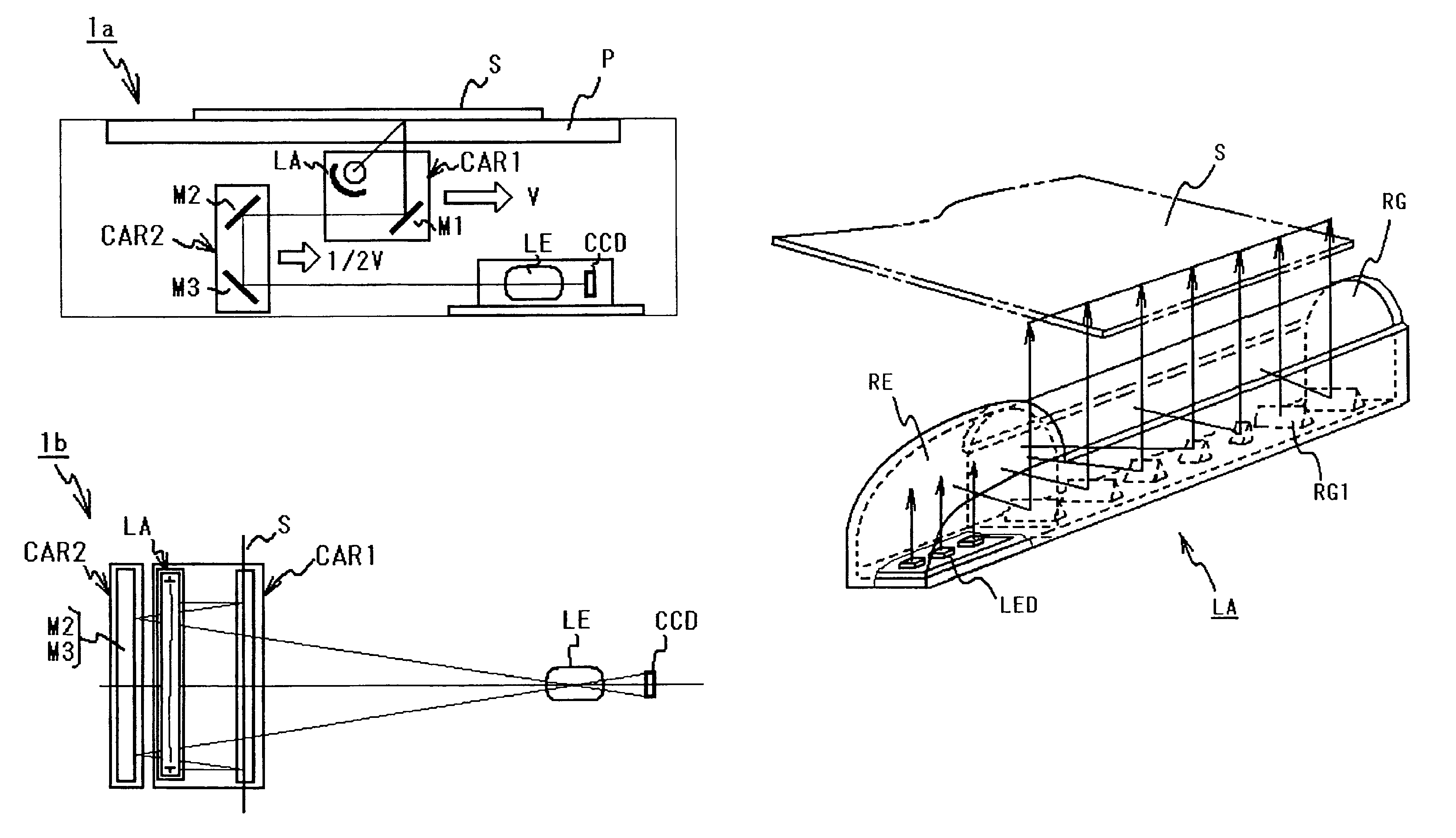
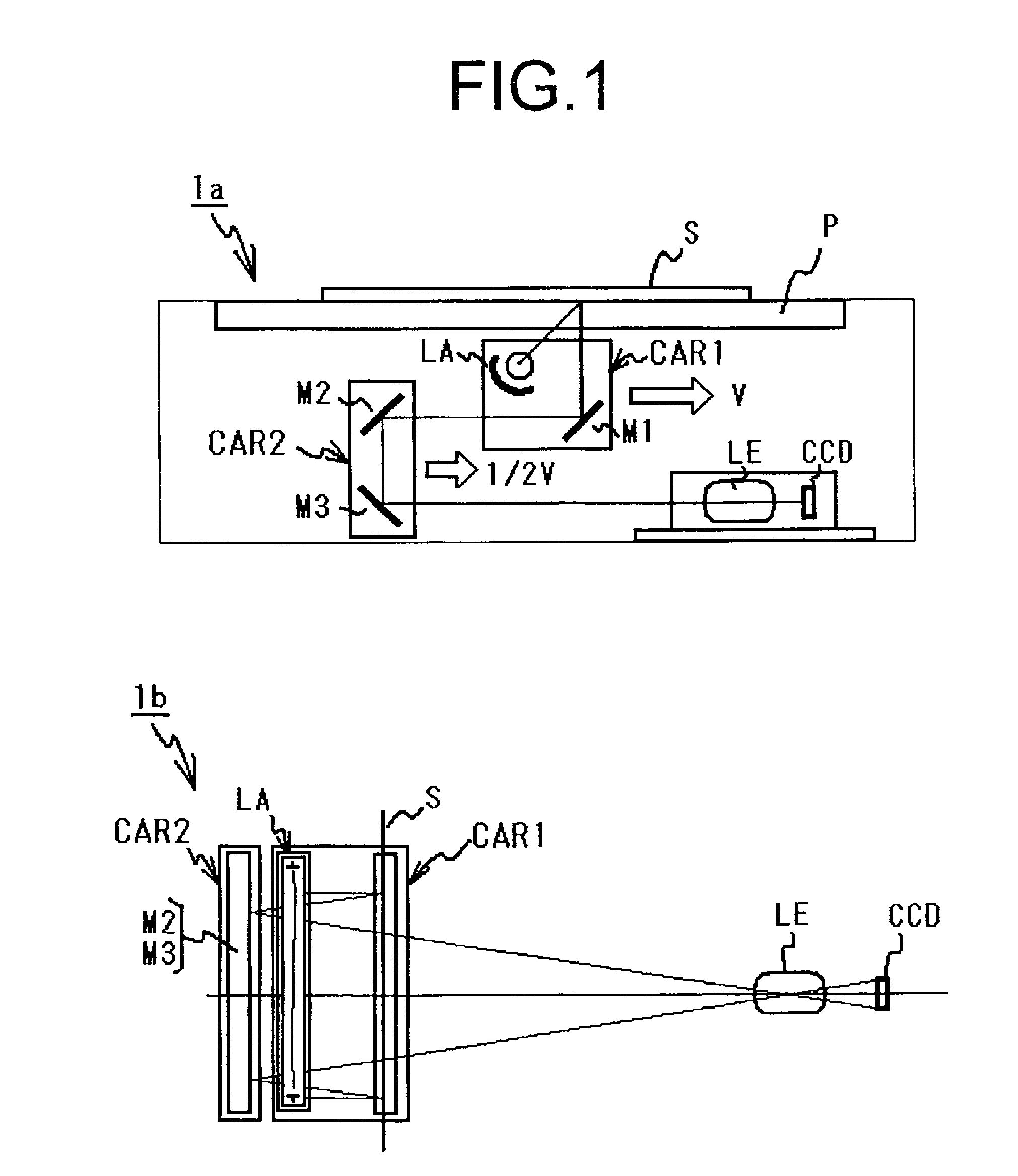
[0061]FIG. 14 contains configuration diagrams showing a schematic configuration of a contact image sensor type image reading apparatus according to the invention, where FIG. 14a is a configuration diagram of the apparatus, and FIG. 14b is a schematic view of the contact image sensor as viewed from the read original side.

[0062]The entire apparatus configuration will be described first based on FIG. 14a. The apparatus is comprised of a platen P for mounting a read original S, and a carriage body having an LED light source LA for lighting an original surface of the read original S placed on a mount surface of the platen P, a Selfoc lens SL for condensing the reflected light from an o...


PUM


Abstract

An LED light source device installed in an image reading apparatus, includes an LED that is a light-emitting source; and a light guide for reflecting light of the LED by an inner surface thereof to diffuse along a main scanning line direction and irradiating the light reflected by the light guide to a surface of a sheet. The light guide has a plurality of reflecting surface bodies spaced at predetermined pitches in the main scanning line direction inside an inner surface reflection optical path to reflect the light from the LED toward an outside along the main scanning line direction. The plurality of reflecting surface bodies includes a first reflecting surface body and a second reflecting surface body, and a length in a perpendicular direction to the main scanning line direction of the second reflecting surface body is different from that of the first reflecting surface body.

Description

BACKGROUND OF THE INVENTION[0001]The present invention relates to an LED light source with an LED as a light-emitting source used in an image reading apparatus as a light source, and an optical reduction type image reading apparatus using the LED light source as a light source.[0002]Conventionally, as this kind of optical reduction type image reading apparatus, for example, such an apparatus has been known in Patent Document 1 [Japanese Laid-Open Patent Publication No. 2002-101263]. In FIG. 1, as shown in FIG. 1a, the optical reduction type image reading apparatus is comprised of a platen P for mounting a read original S, a first carriage body having a light source LA for lighting an original surface of the read original S placed on a mount surface of the platen P and a reflector M1 for reflecting the reflected light from the original surface of the read original S, a second carriage body having reflectors M2 and M3 for guiding the reflected light of the reflector M1 to a light-rece...

Claims


Application Information

Patent Timeline
Patent Type & Authority Patents(United States)
IPC IPC(8): H04N1/04F21V9/40
CPCG02B6/0038H04N1/02815H04N1/02835H04N1/02885G02B6/0061
Inventor SAKAMOTO, FUMIHIDEKAGAMI, YUICHITANAKA, SATOSHI
Owner NISCA KK
Why Eureka
Try Eureka