Three-dimensional ultrasonic inspection apparatus

a three-dimensional, ultrasonic technology, applied in the direction of instruments, image data processing, material analysis, etc., can solve the problem of difficulty for users to correctly determine whether the state of the joined area is sound

Inactive Publication Date: 2013-07-16
KK TOSHIBA
View PDF11 Cites 4 Cited by
  • Summary
  • Abstract
  • Description
  • Claims
  • Application Information

AI Technical Summary

Benefits of technology

[0021]The three-dimensional ultrasonic inspection apparatus according to the present invention can make increased visibility determining whether the state of joined area is sound or not in comparison to the known ultrasonic inspection apparatus then provide the state of joined area, determined on the basis of the three-dimensional image of the joined area to user. Further, since the three-dimensional ultrasonic inspection apparatus according to the present invention can display the determination result whether the state of joined area is sound or not together with the three-dimensional image of the joined area, the three-dimensional ultrasonic inspection apparatus according to the present invention can provide more accurate inspection result to user. Furthermore, in the three-dimensional ultrasonic inspection apparatus according to the present invention, since an accuracy of the determination result whether the state of joined area is sound or not can be increased in comparison to the known ultrasonic inspection apparatus, an accuracy of the three-dimensional ultrasonic inspection can be also increased.

Problems solved by technology

However, in case of the known three-dimensional ultrasonic inspection apparatus as described in the Patent Document 2, the state of the joined area displayed in the three-dimensional image of the joined area (the joined area image) is not always displayed in a state where the user can easily determine whether the state of the joined area is sound or not.
Therefore, in this example case, even if the user views (checks) the joined area image, it is difficult for the user to correctly determine whether the state of the joined area is sound or not.

Method used


Image

  • Three-dimensional ultrasonic inspection apparatus
  • Three-dimensional ultrasonic inspection apparatus
  • Three-dimensional ultrasonic inspection apparatus

Examples


Embodiment Construction

[0028]Hereinafter, embodiments of a three-dimensional ultrasonic inspection apparatus according to the present invention will be described with reference to the accompanying drawings.

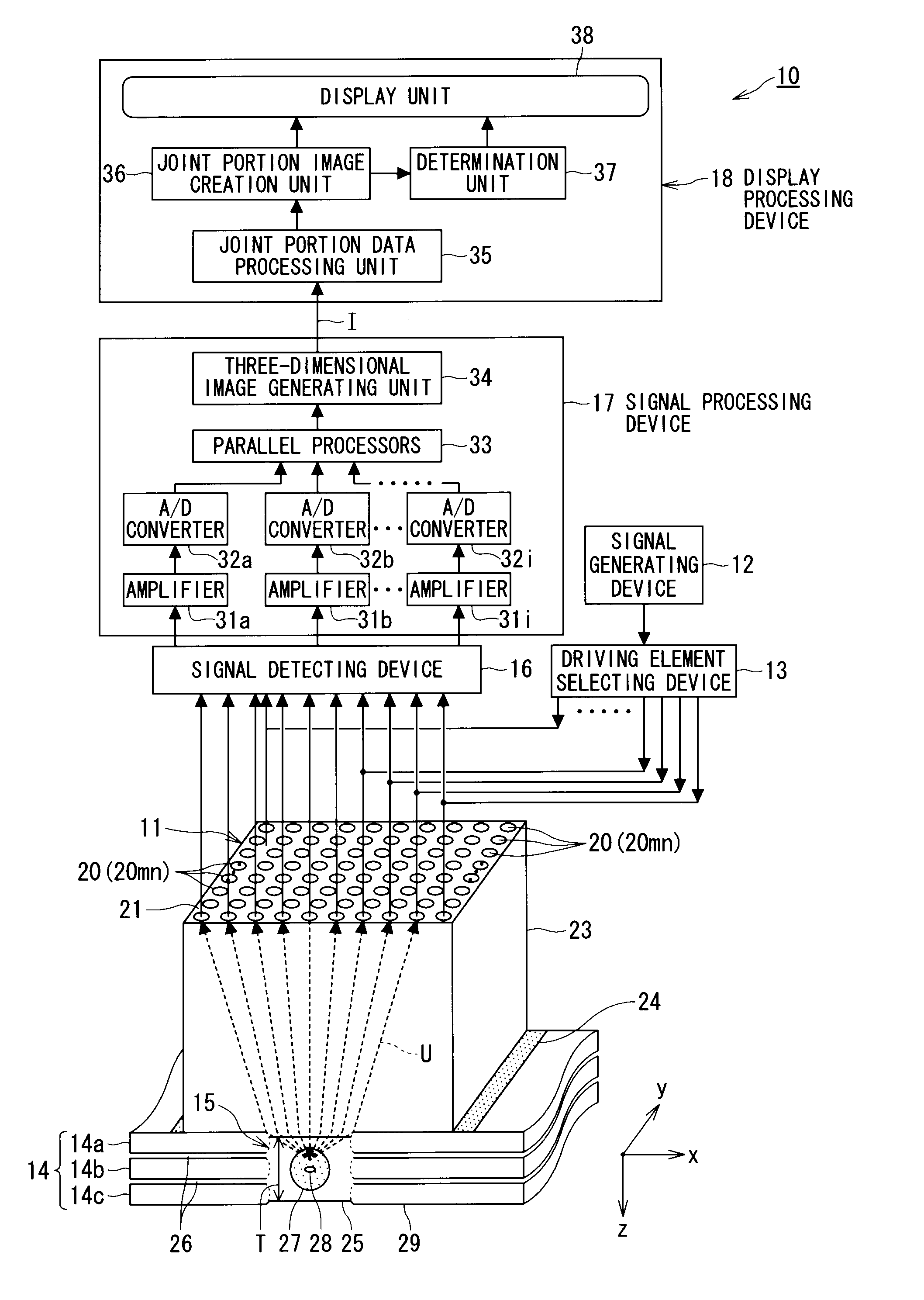
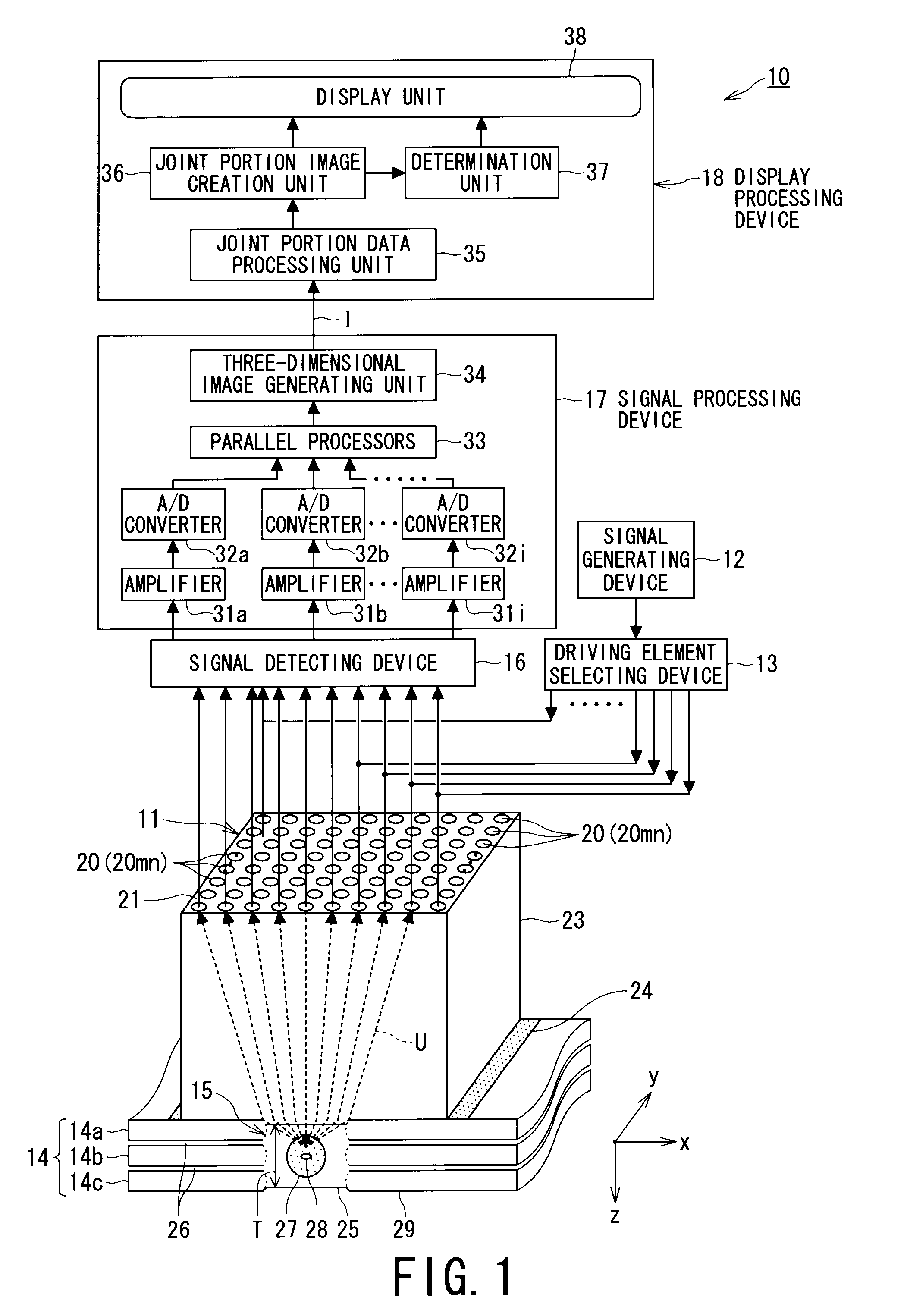
[0029]FIG. 1 is a configuration view schematically illustrating a three-dimensional ultrasonic inspection apparatus 10 serving as one embodiment of the three-dimensional ultrasonic inspection apparatus according to the present invention.

[0030]The three-dimensional ultrasonic inspection apparatus 10 includes: a transducer 11 as an ultrasonic sensor that causes an ultrasonic vibration to be converted into an electric signal and vice versa, and emits and receives an ultrasonic wave having an required frequency; a signal generating device 12 for generating a drive signal for driving the ultrasonic transducer 11; a driving element selecting device 13 for selectively driving a piezoelectric vibrator of the ultrasonic transducer 11 by selecting a drive signal of the signal generating device 12; a signal detect...


PUM


Abstract

A three-dimensional ultrasonic inspection apparatus includes: an ultrasonic transducer disposed m×n piezoelectric vibrators in a matrix; a signal processing device to receive, detect an echo, and generate a three-dimensional image data by processing an electric signal of the echo detected; and a display processing device to display a result of processing the three-dimensional image data generated by the signal processing device, wherein the display processing device includes a peak detecting unit to detect a first peak and a second peak of an intensity distribution of the three-dimensional image data in a depth (z) direction, a joint portion image creation unit to create a three-dimensional image of the joined area by mapping z direction distance of the first peak and the second peak to x-y plane, a determination unit to determine whether the joined area is sound or not, and a display unit to display the three-dimensional image and the determination result of the joined area.

Description

TECHNICAL FIELD[0001]The present invention relates to a three-dimensional ultrasonic inspection apparatus which performs non-destructive inspection of an inner structure, the state of joined area, and the state of a defect of an object to be inspected, using ultrasonic waves, and more specifically, relates to a three-dimensional ultrasonic inspection apparatus including a sensing device for the ultrasonic inspection, used for an ultrasonic imaging apparatus that three-dimensionally visualizes the state of a welded portion and the state of a weld defect of the object to be inspected.BACKGROUND ART[0002]An example of technologies that perform non-destructive inspection of the state of a welded portion and the state of a weld defect of a joined area between plate-like structures, an object to be inspected, is an ultrasonic test technology. In an ultrasonic inspection apparatus which adopts the ultrasonic test technology, the ultrasonic waves are irradiated to the welded area of the obj...

Claims


Application Information

Patent Timeline
Patent Type & Authority Patents(United States)
IPC IPC(8): G06K9/00A61K49/00
CPCG01N29/069G01N29/262G01N2291/106G01N2291/267
Inventor MATSUMOTO, SHINIKEDA, TAKAHIROKARASAWA, HIROKAZU
Owner KK TOSHIBA
Why Eureka
Try Eureka