Formation modeling while drilling for enhanced high angle for horizontal well placement

a technology of formation modeling and horizontal well placement, which is applied in the field of formation modeling while drilling for enhanced high angle for horizontal well placement, can solve the problems of inconsistencies in model-based interpretations and adversely affect the modeling of formations, and achieve the effect of optimizing the use of all available computing resources

Active Publication Date: 2013-07-16
SCHLUMBERGER TECH CORP
View PDF8 Cites 48 Cited by
  • Summary
  • Abstract
  • Description
  • Claims
  • Application Information

AI Technical Summary

Benefits of technology

[0031]In another refinement, the HPC infrastructure 201 with a plurality of computing resources on the network, local (Intranet) or global (Internet), is linked to a plurality of wellsites and the HPC infrastructure 201 comprises parallelization, scheduling and load-balancing for the computing of multiple algorithms, insuring optimal use of all available computing resources.

Problems solved by technology

However, the following common scenarios can adversely affect the modeling of a formation: nearby boundaries and faults; cross-bedding; layering; eccentralization of the tool in the borehole; effects of invaded fracture swarms with the presence of nearby boundaries; borehole size variation, shape and mud properties; and others.
One or more of these scenarios can cause inconsistencies in model-based interpretations, be they in real-time or post-drilling.

Method used


Image

  • Formation modeling while drilling for enhanced high angle for horizontal well placement
  • Formation modeling while drilling for enhanced high angle for horizontal well placement
  • Formation modeling while drilling for enhanced high angle for horizontal well placement

Examples


first embodiment

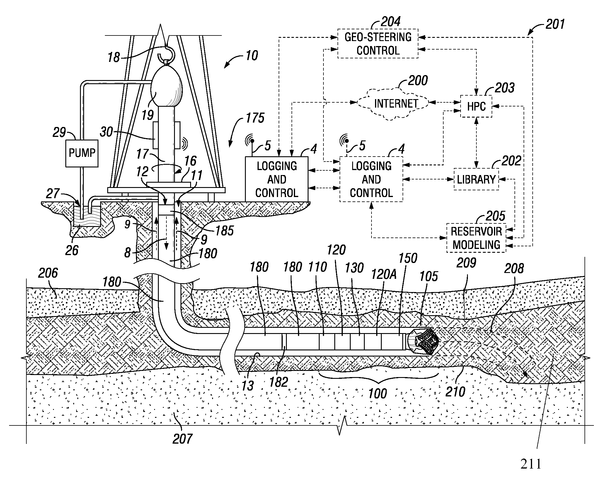
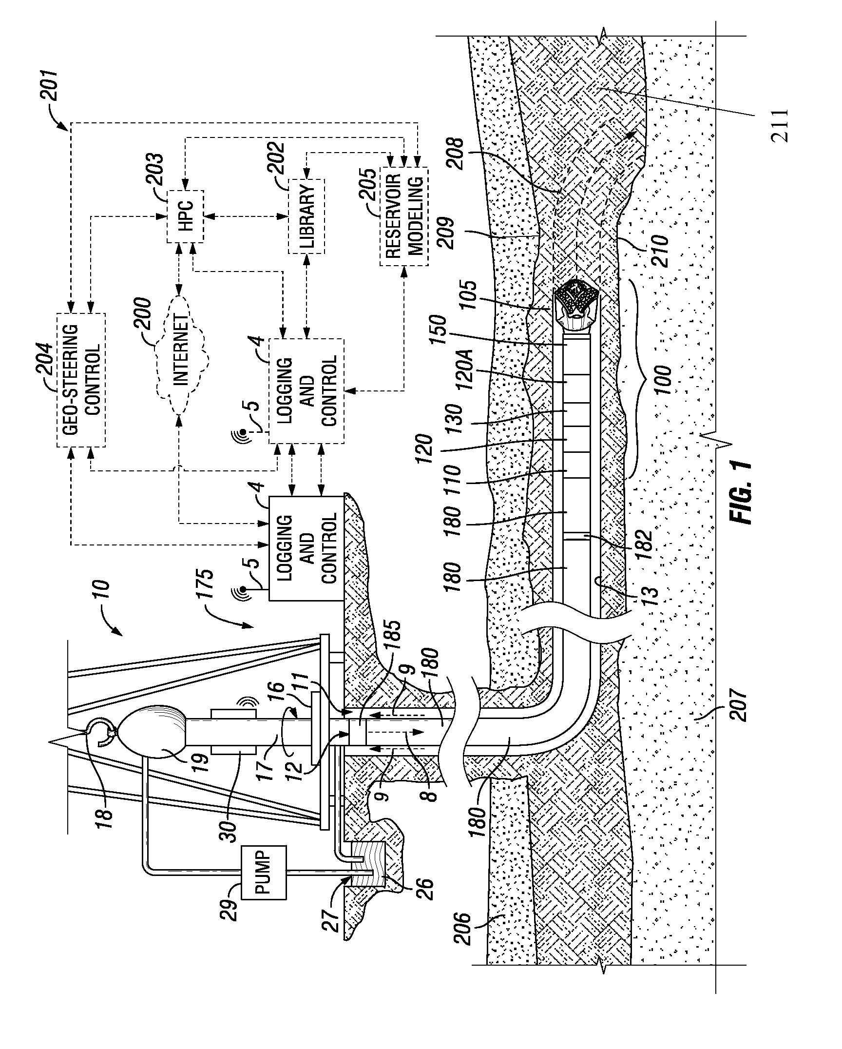
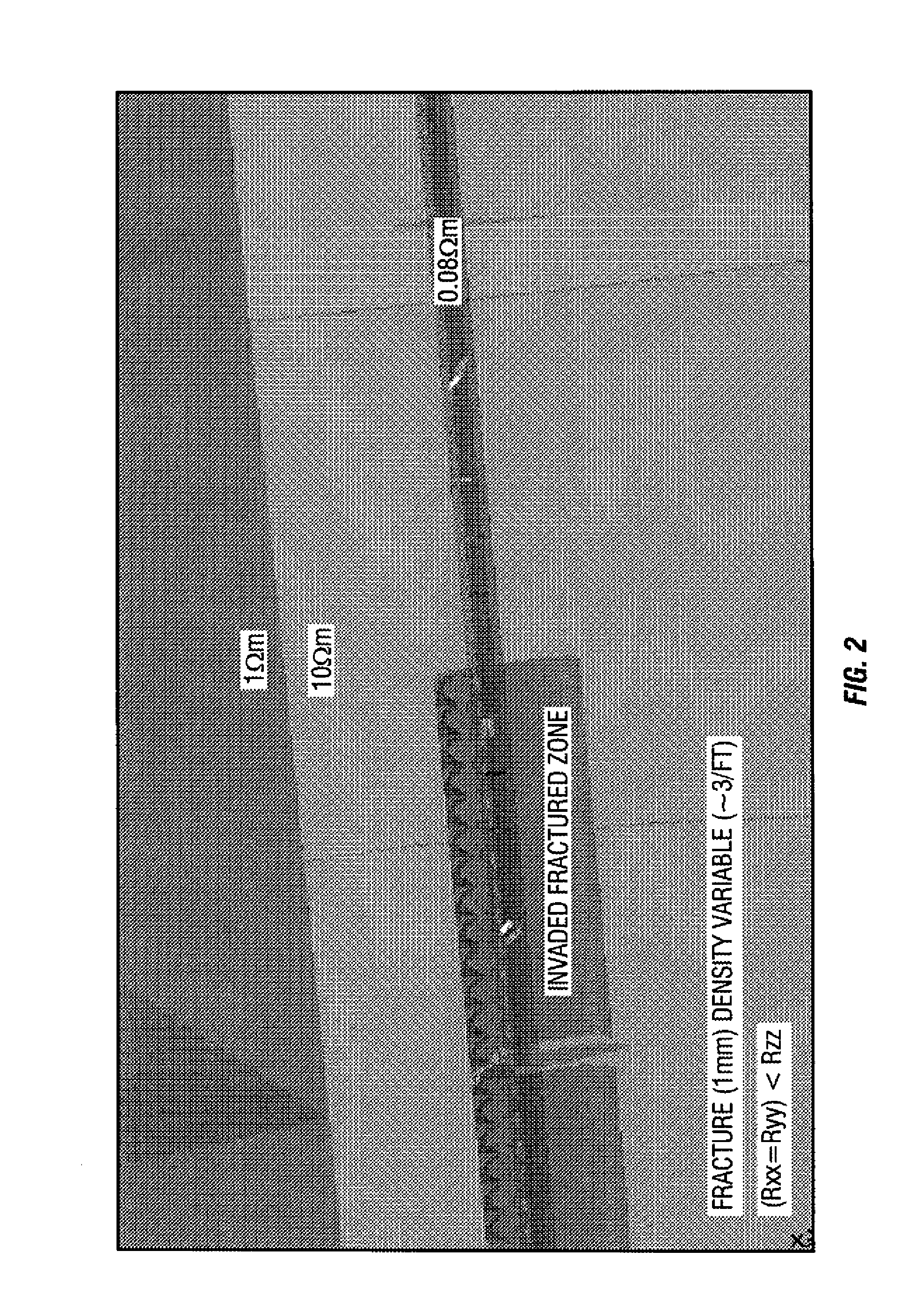
[0053]In a first embodiment, a disclosed technique starts with a seismic reservoir model in PETREL™ software used for while drilling visualization of well path in reservoir 3D structure, as well as visualization and integration of all measurement and drilling data. Then, a section of the reservoir model is extracted for a given well trajectory 208 and that is the depth of investigation of the tool or tools 120, 130, 120A. Tool response modeling is performed for a given interval of the wellbore trajectory 208. A “domain of interest” or an area of interest of the model is identified where statistical uncertainty is high between tool response modeling and the initial reservoir model. Possible changes in the model are identified that are not present in the original reservoir model, such as borehole fluid invasion effects, including the shape of the borehole, invasion profile, anisotropy, cross-bedding, sub-seismic faults, etc. Various parameters assigned to the area of interest include,...

second embodiment

[0055]In a second embodiment, a model update feature is based on 2D / 3D forward modeling. In this embodiment, an existing (e.g. seismic) reservoir model in PETREL™ is used. Then, a section of the reservoir model for a given well trajectory that is also defined by the tool depth of investigation is extracted. The extracted model may be in the form of curtain section for 2D model, a Pillar grid for a 3D models, or a general corner point grid. Tool response modeling is performed for a given interval of the trajectory. A “domain of interest” or an area of interest is identified for part of the model from that needs refinement, i.e. where there is mismatch between modeled data and tool measurements. Potential geologically feasible models are identified that may be appropriate for the given area of interest. Parameters for the area of interest are identified and defined. Such parameters include, but are not limited to: parameters relating to nearby boundaries including position, their dip ...

fourth embodiment

[0059]In the fourth embodiment, a combination of well placement tools may be employed such as an azimuthal resistivity imaging tool (e.g., Schlumberger's GEOVISION™ resistivity imaging tools or resistivity at the bit (RAB) tools) and curtain section imaging tools (e.g., Schlumberger's PERISCOPE™ deep imaging resistivity tools). The multiple tool responses are used to refine the reservoir models.


PUM


Abstract

LWD measurements to be used for proactive well placement while drilling a high angle or horizontal wellbore in a reservoir are defined. An initial reservoir model is provided and a section is extracted for a planned wellbore trajectory. A secondary model is generated for the planned trajectory. An area of interest is identified where statistical uncertainty is high. Possible causes of the statistical uncertainty are identified that are not present in the initial reservoir model. A set of parameters are defined based on the possible causes of statistical uncertainty. The area of interest is logged with LWD tool. Sensitivities of the LWD tool response to a subset of parameters are evaluated by performing tertiary model for a range of the subset of parameters. The most sensitive parameters from the subset of parameters and corresponding measurements are identified. LWD measurements are defined based on the most sensitive parameters.

Description

CROSS REFERENCE TO RELATED APPLICATIONS[0001]This application claims priority to U.S. Provisional Application Ser. No. 60 / 981,762, filed on Oct. 22, 2007 and entitled “Well Placement in Complex Reservoirs and Improved 3D Structure Characterization in Horizontal Wells using Azimuthal Measurements while Drilling.”BACKGROUND[0002]1. Technical Field[0003]This disclosure relates generally to oil and gas well logging and directional drilling. More specifically, techniques are disclosed for enhancing well placement using logging while drilling (LWD) tool data to update or change the reservoir model while drilling, or after drilling. Continuously updating the reservoir model enhances the ability to geo-steer the drill string to the desired location in high angle or horizontal (HA / HZ) wellbores. The disclosed techniques include improved 1D, 2D, 2.5D and 3D modeling methods while drilling using directional electromagnetic, borehole imaging and bit resistivity data. Methods for processing such...

Claims


Application Information

Patent Timeline
Patent Type & Authority Patents(United States)
IPC IPC(8): G06G7/48
CPCG01V11/00
Inventor OMERAGIC, DZEVATHABASHY, TAREK M.POLYAKOV, VALERYKOCIAN, RAYMONDCHEN, YONG-HUADAVYDYCHEVA, SOFIAALTMAN, RAPHAELMAESO, CARLOSHUPP, DOUGLAS
Owner SCHLUMBERGER TECH CORP
Why Eureka
Try Eureka