
Server location mapping

a server and location technology, applied in error detection/correction, program control, instruments, etc., can solve the problems of increasing complexity and cost of server management, consuming significant amounts of power, and seemingly mundane tasks, and achieve the effect of eliminating human errors

Active Publication Date: 2013-07-16
ORACLE INT CORP
View PDF8 Cites 0 Cited by
  • Summary
  • Abstract
  • Description
  • Claims
  • Application Information

AI Technical Summary

Benefits of technology

The patent text is about a system that can automatically determine the locations of multiple computers without relying on human error. This helps to ensure that the computers are properly organized and can communicate with each other effectively.

Problems solved by technology

Managing these servers is becoming an increasingly complicated and expensive task.
Moreover, servers typically consume significant amounts of power depending upon load.
However, this seemingly mundane task is complicated by the sheer magnitude of the number of servers.
For example, manually collecting and storing server locations for thousands of servers is a tedious and error-prone task.
Moreover, the locations of specific servers can change over time as system operators replace, upgrade and relocate assets in a data center, which makes it even more difficult to maintain accurate server location information.

Method used


Image

  • Server location mapping
  • Server location mapping
  • Server location mapping

Examples


Embodiment Construction

[0024]The following description is presented to enable any person skilled in the art to make and use the invention, and is provided in the context of a particular application and its requirements. Various modifications to the disclosed embodiments will be readily apparent to those skilled in the art, and the general principles defined herein may be applied to other embodiments and applications without departing from the spirit and scope of the present invention. Thus, the present invention is not intended to be limited to the embodiments shown, but is to be accorded the widest scope consistent with the principles and features disclosed herein.

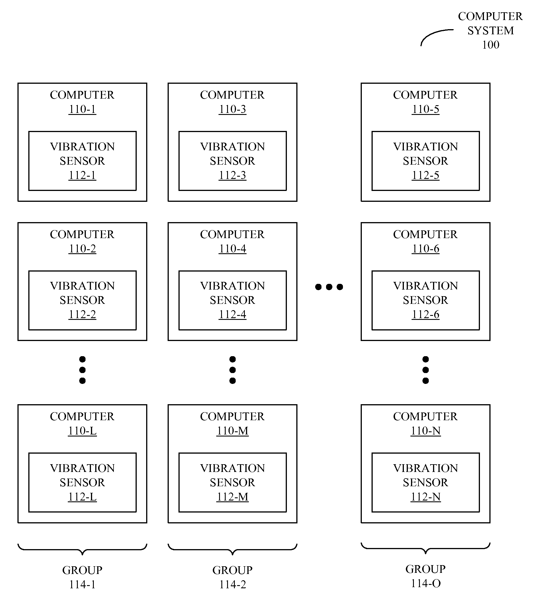
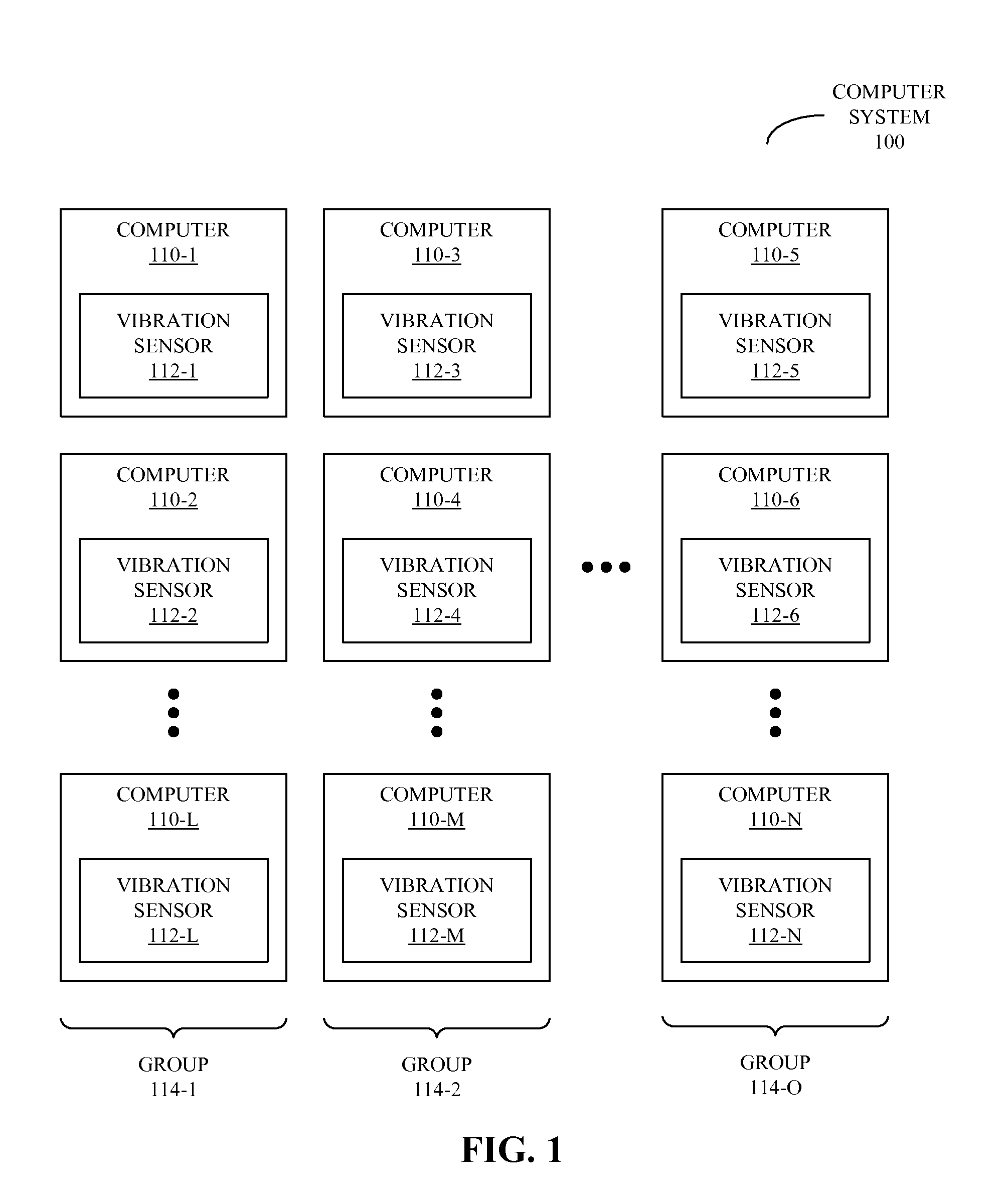
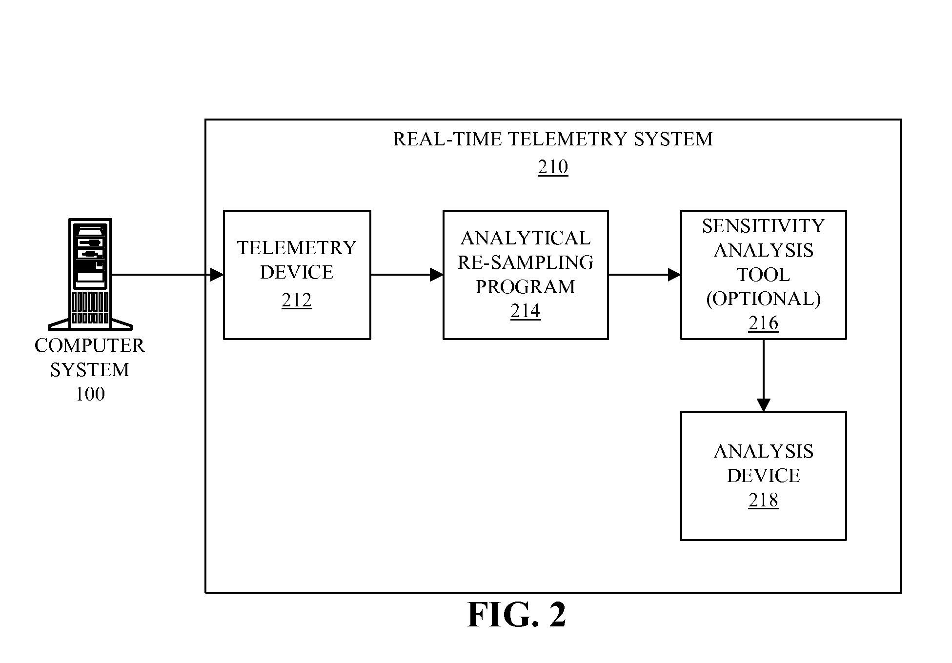
[0025]Embodiments of a system (such as a computer system), a method, and a computer-program product (i.e., software) for use with the system are described. These systems and processes may be used to perform in-situ measurements of vibration spectra for multiple computers (such as servers) in a group of computers (which may be included in the co...


PUM


Abstract

Embodiments of a method for determining locations of computers in a group of computers, which may be performed by a system, are described. During operation, the system receives a location of a first computer in the group of computers. Then, the system determines locations of one or more additional computers in the group of computers relative to the first computer based on vibration spectra associated with the first computer and the one or more additional computers.

Description

BACKGROUND[0001]1. Field of the Invention[0002]The present invention generally relates to devices and techniques for monitoring a computer system. More specifically, the present invention relates to techniques for determining locations of servers in a data center based on vibration spectra.[0003]2. Related Art[0004]Modern data centers typically contain hundreds and even thousands of servers. Managing these servers is becoming an increasingly complicated and expensive task. For example, different servers within the same data center may be configured differently and may consequently require different software and different drivers. Moreover, servers typically consume significant amounts of power depending upon load. Consequently, the resulting thermal load and the associated cooling requirements for servers can vary dynamically, as different workloads are executed over time.[0005]In order to address these challenges and effectively manage a data center, it is useful to be able to dete...

Claims


Application Information

Patent Timeline
Patent Type & Authority Patents(United States)
IPC IPC(8): G06F15/173
CPCG06F15/173G06F9/5094G06F11/3006G06F11/3044G06F11/3058Y02D10/00G06F11/30
Inventor LEWIS, ANDREW J.GROSS, KENNY C.URMANOV, ALEKSEY M.
Owner ORACLE INT CORP
Learn More