Afterburner chamber for a turbomachine

a turbomachine and afterburner technology, which is applied in the direction of machines/engines, burner ignition devices, lighting and heating apparatus, etc., can solve the problems of difficulty or failure in igniting the afterburner chamber, and the fuel ejector holes in the vicinity of the spark plug becoming at least partially blocked

Active Publication Date: 2013-07-23
SN DETUDE & DE CONSTR DE MOTEURS DAVIATION S N E C M A
View PDF8 Cites 3 Cited by
  • Summary
  • Abstract
  • Description
  • Claims
  • Application Information

AI Technical Summary

Benefits of technology

[0009]This specific ventilation of the orifices in the fuel strip in the immediate vicinity of the spark plug avoids these orifices becoming coked and solves the problems of igniting the afterburner.
[0010]The quantity of air conveyed to the vicinity of the spark plug remains unchanged, only the flow of the air stream in the vicinity of the orifices in the strip is modified, thereby serving to avoid changing the richness of the air-fuel mixture (i.e. the ratio of the fuel flow rate divided by the associated air flow rate), and thus makes it possible to conserve the same performance for the afterburner chamber.
[0011]According to another characteristic of the invention, the ventilation means include orifices formed in the upstream wall of the protection tube and pointing towards the spark plug, thereby enabling the ventilation air to be directed preferentially towards those ejector orifices of the strip that are adjacent to the spark plug.
[0012]Advantageously, the orifices in the upstream wall of the protection tube are in alignment with air-passing orifices in the burner ring, thereby enabling a fraction of the air flow to be pointed directly towards the orifices in the strip in the immediate vicinity of the spark plug, thus optimizing ventilation for avoiding the formation of coke.

Problems solved by technology

In operation, the fuel ejector holes in the vicinity of the spark plug are nevertheless subjected to a fuel coking phenomenon because of the intense heat that exists in this zone, with this phenomenon leading to the fuel ejector holes in the vicinity of the spark plug becoming at least partially clogged and to difficulties or failures in igniting the afterburner chamber.

Method used


Image

  • Afterburner chamber for a turbomachine
  • Afterburner chamber for a turbomachine
  • Afterburner chamber for a turbomachine

Examples


Embodiment Construction

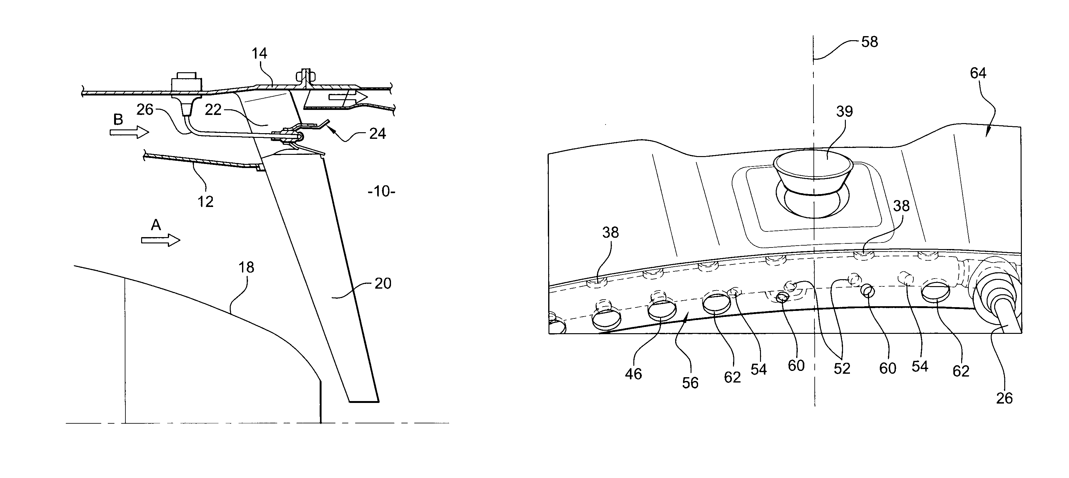
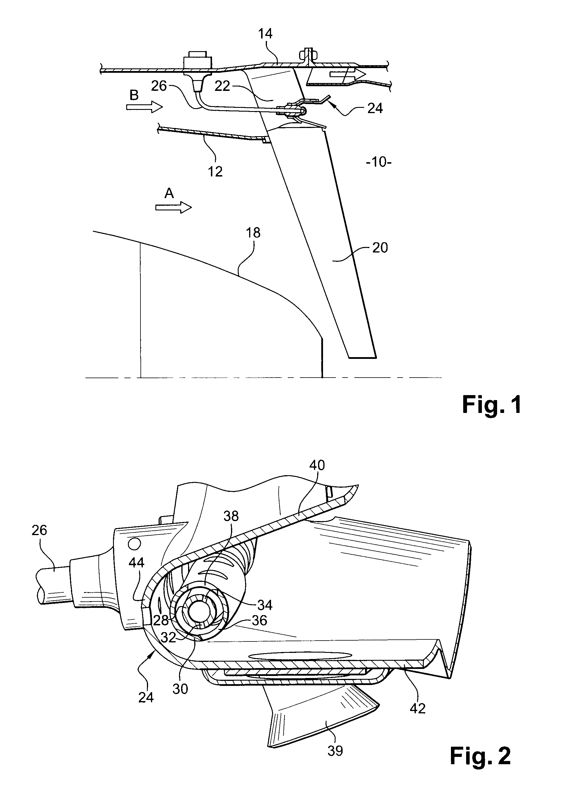
[0022]Reference is made initially to FIGS. 1 and 2 that show a prior art afterburner chamber 10 situated between the turbine and the outlet nozzle of a bypass turbojet.

[0023]The afterburner chamber 10 has a substantially cylindrical wall 12 separating the primary and secondary streams (arrows A and B respectively), which wall is mounted inside an outer cylindrical exhaust casing 14 and around an exhaust cone 18 of the turbojet. The wall 12 and the casing 14 define between them an outer annular flowsection in which there flows the cool or secondary stream (arrow B) of the turbojet as generated by a fan at the upstream end of the turbojet and serving both to increase thrust and to ventilate the components of the turbojet. The wall 12 co-operates with the exhaust cone 18 to define an inner annular flowsection in which there flows the hot or primary stream (arrow A) of the turbojet, which stream is constituted by the exhaust gas from the combustion chamber of the turbojet. The primary a...


PUM


Abstract

An afterburner chamber includes a burner ring having housed therein an annular fuel strip that is pierced by orifices and that is mounted inside an annular thermal protection tube, and an ignition spark plug penetrating into the inside of the burner ring. The protection tube and the burner ring have orifices for passing air. The chamber also includes a device for ventilating the orifices of the fuel strip that are situated in the immediate vicinity of the spark plug.

Description

FIELD OF THE INVENTION[0001]The present invention relates to an afterburner chamber for a turbomachine such as a bypass turbojet for an airplane.BACKGROUND OF THE INVENTION[0002]In conventional manner, a turbojet with afterburning comprises from upstream and downstream in the flow direction of the gas: at least one compressor; a combustion chamber; and at least one turbine with a reheat channel or afterburner chamber.[0003]In general, the afterburner chamber comprises a burner ring that is open in a downstream direction and that has mounted therein a fuel ejector strip that is placed inside an annular thermal protection tube. The ejector strip is connected to fuel feeder means and includes ejector holes pointing downstream and in alignment with holes in the thermal protection tube. A spark plug is mounted on the burner ring and penetrates into the inside of the ring in the proximity of the fuel strip in order to ignite the fuel.[0004]Air-passing orifices are formed in the burner rin...

Claims


Application Information

Patent Timeline
Patent Type & Authority Patents(United States)
IPC IPC(8): F02K3/10
CPCF02C7/266F02K3/11F23R3/20F23D2207/00Y02T50/676F05D2260/20Y02T50/60
Inventor LAINS, DOMINIQUE MAURICE JACQUESLEBLOND, NICOLASSANDELIS, DENIS JEAN MAURICE
Owner SN DETUDE & DE CONSTR DE MOTEURS DAVIATION S N E C M A
Why Eureka
Try Eureka