
Line system arrangement in an aircraft or spacecraft having a fuselage

a technology of fuselage and system arrangement, which is applied in the direction of aircraft crew accommodation, transportation and packaging, and can solve the problems of inability to achieve, disadvantageous in economic efficiency, and limited space within the fuselage, and achieve the effect of reducing the installation work within the fuselag

Inactive Publication Date: 2013-07-23
AIRBUS OPERATIONS GMBH
View PDF18 Cites 2 Cited by
  • Summary
  • Abstract
  • Description
  • Claims
  • Application Information

AI Technical Summary

Benefits of technology

[0006]Against this background, it is one of the objects of the pre-sent invention to provide an improved arrangement of a line system in a fuselage of an aircraft or spacecraft, which arrangement no longer has or very largely eliminates the above-mentioned disadvantages and which, in particular, reduces the installation work within the fuselage.
[0008]In comparison to the approaches mentioned at the beginning, the present invention therefore may achieve the advantage that the line systems can be fitted from the outside into receiving regions provided for them, with, during the installation, the interior space being kept free for other work. Furthermore, there may be a considerable advantage in that the line systems can be predominantly premanufactured separately, as a result of which the fitting time is additionally advantageously reduced. The effect achieved by the invention may be that a time saving during assembly is advantageously increased by approximately 60%.
[0010]In one particular embodiment, it is provided that the at least one receiving region extends along an inner wall of the fuselage in a longitudinal direction of the fuselage or at an angle to the longitudinal direction. This results in regions for which premanufacturing or preassembly of the line systems is advantageously suitable, and produces an additional time saving.
[0011]In this case, the arrangement may include a pressure-tight separating device for pressure-tight separation of the at least one receiving region from an interior space of the fuselage. This affords the advantage that the receiving regions, which are accessible from the outside, can be closed by coverings which can be removed again, without a special pressure-tight encapsulation having to take place after installation or again during maintenance.
[0014]A particular advantage may reside in the fact that the at least one receiving region is arranged outside an impact region of the fuselage. The probability that, even in the event of an impact, systems will continue to maintain their function is therefore increased.

Problems solved by technology

In this connection, however, there is the problem that space within the fuselage is limited and it is not possible to carry out all work at the same time, which is disadvantageous in terms of economic efficiency.
Furthermore, it is problematic that the line systems can be premanufactured only to a small extent.

Method used


Image

  • Line system arrangement in an aircraft or spacecraft having a fuselage
  • Line system arrangement in an aircraft or spacecraft having a fuselage
  • Line system arrangement in an aircraft or spacecraft having a fuselage

Examples


Embodiment Construction

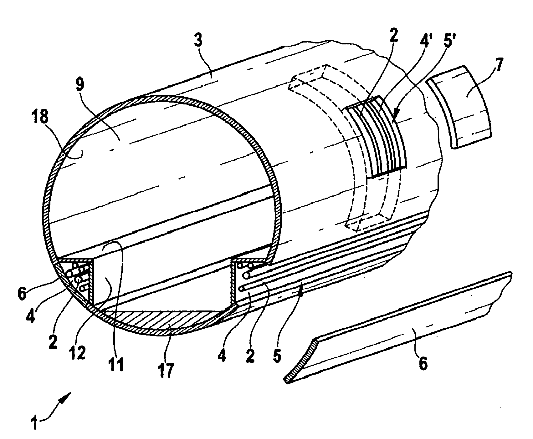
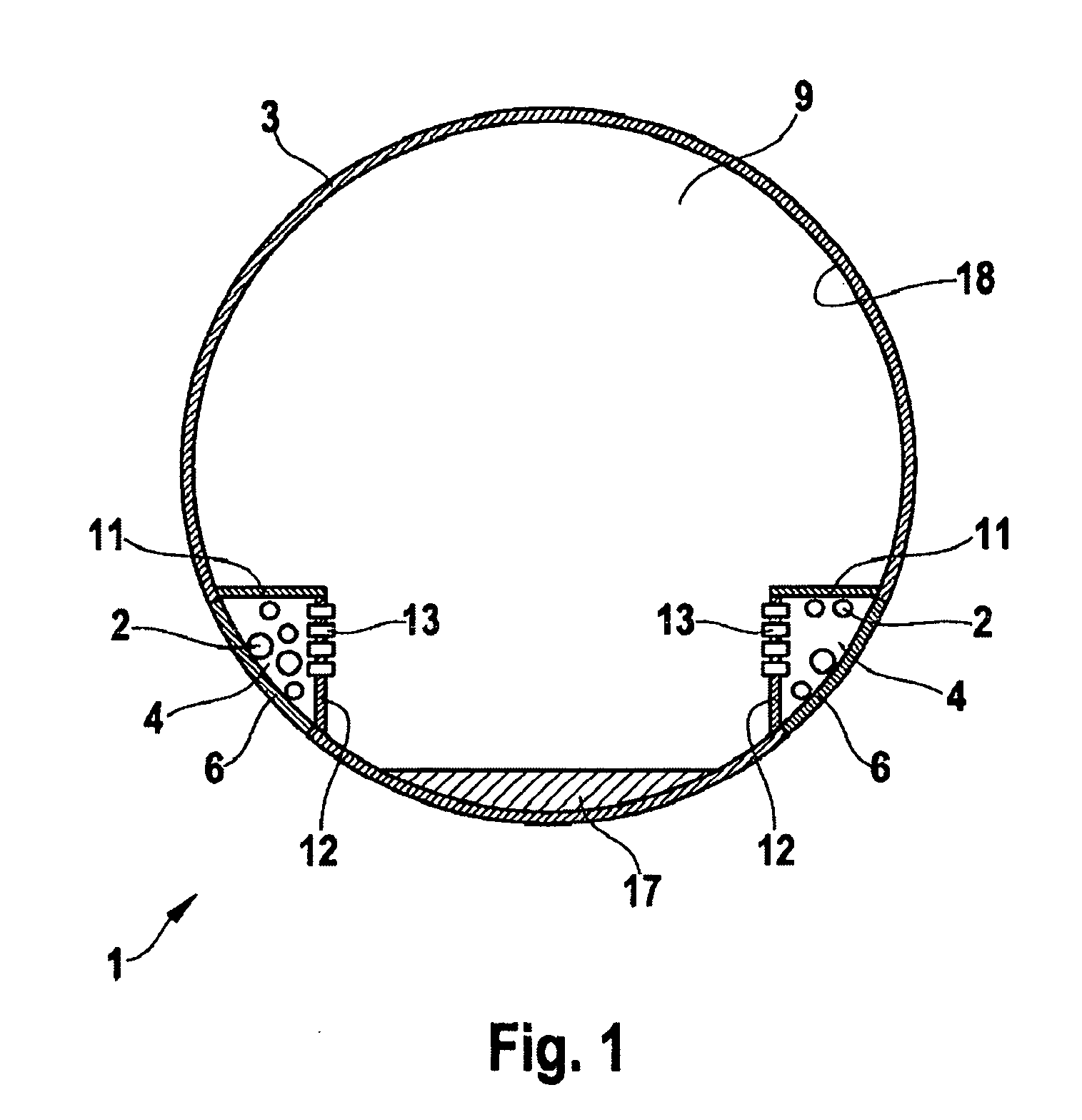
[0021]FIG. 1 shows a cross-sectional view of a fuselage 3 of a line system arrangement 1 according to an exemplary embodiment of the present invention.

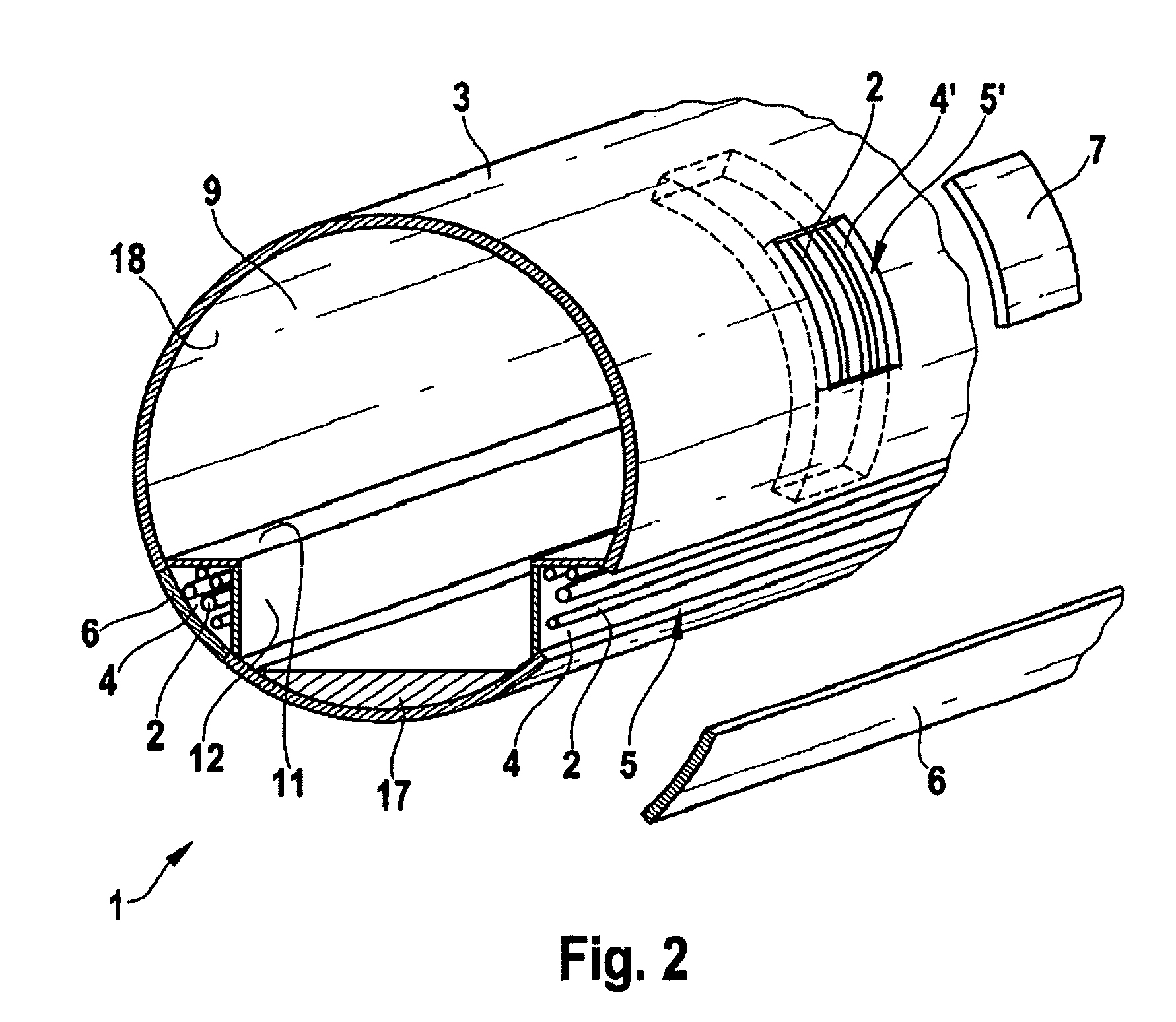
[0022]In this example, the fuselage 3 has a circular cross section and is a fuselage of an aircraft which is not shown specifically. The fuselage 3 encloses a first interior space 9 which is enclosed in a pressure-tight manner by an inner wall 18 of the fuselage 3. An “impact region”17, which is also referred to as a crash area, is arranged in the lower region of the fuselage 3. In this example, above the impact region 17 on each side of the fuselage 3 there is arranged a receiving region 4 which is separated in a pressure-tight manner from the first interior space 9 by means of a respective first separating device 11 and second separating device 12. The separating devices 11, 12 therefore form a continuation of the pressure-tight encapsulation of the interior space 9 by the inner wall 18. The cross section of the receiving regions 4 ...


PUM


Abstract

A line system arrangement in an aircraft or spacecraft having a fuselage includes at least one receiving region for receiving at least one component of a line system, wherein the at least one receiving region is accessible, at least in some sections, from outside the fuselage of the aircraft and spacecraft for installation and / or maintenance of the line system; and an aircraft or spacecraft with a corresponding arrangement.

Description

FIELD OF THE INVENTION[0001]The present invention relates to a line system arrangement in an aircraft or spacecraft having a fuselage, with at least one receiving region for receiving at least one component of a line system, and to an aircraft or spacecraft with an arrangement of this type.BACKGROUND OF THE INVENTION[0002]During the final assembly of an aircraft, a great deal of work is to be carried out within the fuselage, such as, for example, installation of various types of line systems.[0003]Line systems of this type and their installation are also referred to as routings and generally comprise lines for liquid and gaseous media, for example water, air, oxygen, etc., and electric signal transmission lines, electric supply lines and potential equalization lines or the like. Fastenings and supporting elements and the like also belong to the components of the line systems.[0004]It is customary to lay these line systems within the fuselage in the region subjected to an internal pr...

Claims


Application Information

Patent Timeline
Patent Type & Authority Patents(United States)
IPC IPC(8): B64C1/00
CPCB64C1/066B64C1/068B64C1/12B64C1/1446B64D11/00B64G1/22H02G3/0418H02G3/0437
Inventor LAUE, HANS-GEORG
Owner AIRBUS OPERATIONS GMBH
Learn More