
Flow cell, apparatus for concentrating radioactive fluoride anion, and method of concentrating radioactive fluoride anion

a technology of radioactive fluoride anion and flow cell, which is applied in the field of flow cell, apparatus for method of concentrating radioactive fluoride anion, can solve the problems of limited time period that can be used for pet or the like, and achieve the effect of high liquid tightness within the channel and high concentration rate of 18f ion

Inactive Publication Date: 2013-07-23
SHIMADZU CORP +1
View PDF11 Cites 1 Cited by
  • Summary
  • Abstract
  • Description
  • Claims
  • Application Information

AI Technical Summary

Benefits of technology

The present invention provides a flowcell for trapping and collecting 18F− ions while a solution containing the 18F− ions is being let to flow. The flowcell includes a pair of electrodes, at least one of which is a carbon electrode made of a pyopolymer in the inside of a channel formed within a cell main body. The carbon electrode can be patterned to have multiple functions by making the channel shape complex. The flowcell has high liquid-tightness and can be easily treated with a slight amount of liquid. The technical effects of this invention are high efficiency in collecting 18F− ions and versatility in flowcell design.

Problems solved by technology

Also, since [18O]—H2O water serving as a source material of the 18F− ion is expensive, reuse of the [18O]—H2O water is desired in order to attain cost-down of the PET diagnosis.
Because of the short life of the radioactive nuclides that are put to use, the period of time that can be used for the PET or the like is limited and, for the synthesis of compounds labeled with reduction of time in terms of minutes and a high synthesis rate are simultaneously demanded.

Method used


Image

  • Flow cell, apparatus for concentrating radioactive fluoride anion, and method of concentrating radioactive fluoride anion
  • Flow cell, apparatus for concentrating radioactive fluoride anion, and method of concentrating radioactive fluoride anion
  • Flow cell, apparatus for concentrating radioactive fluoride anion, and method of concentrating radioactive fluoride anion

Examples


Embodiment Construction

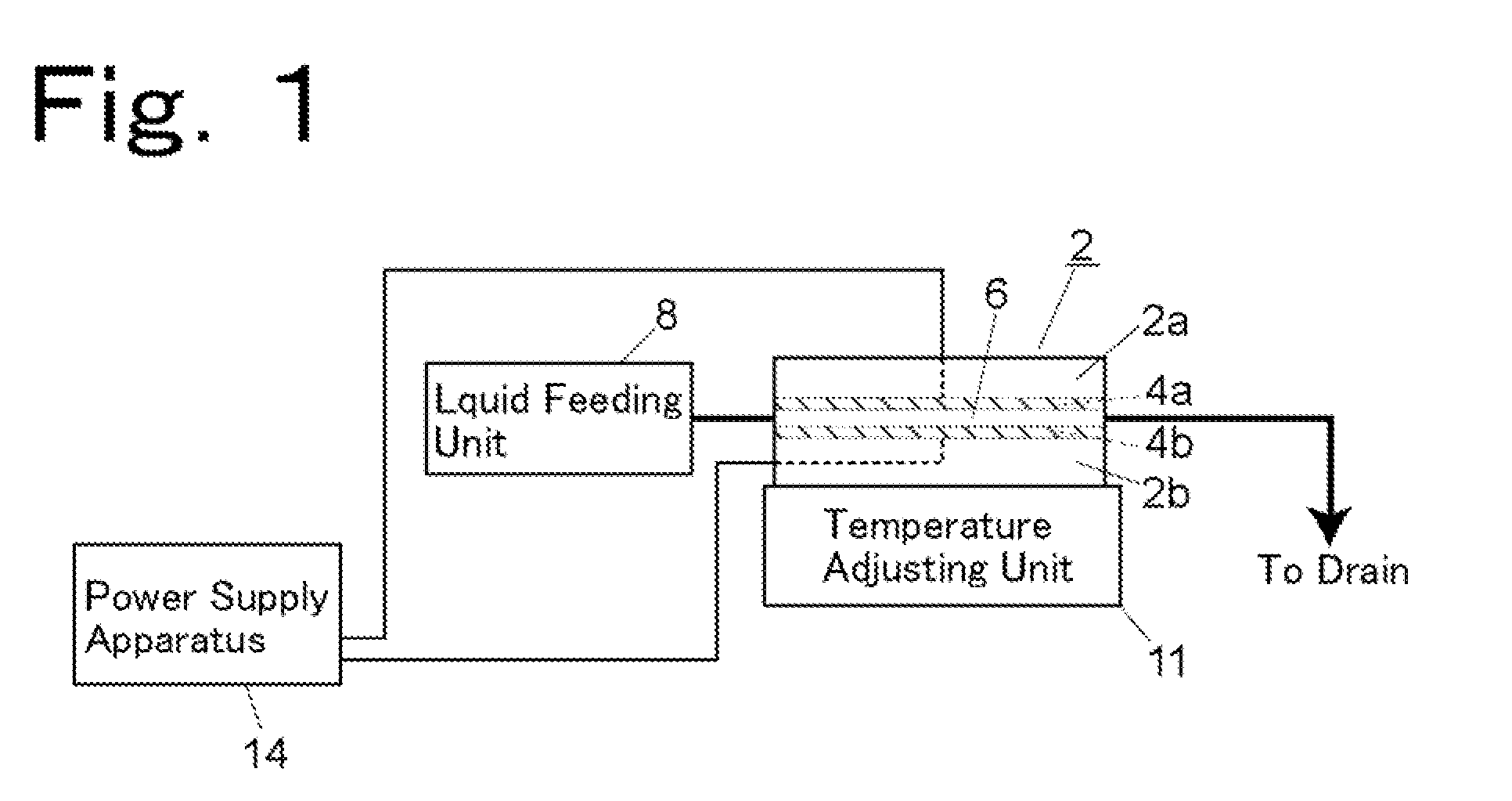
[0055]FIG. 1 is a schematic construction view illustrating, one example of a radioactive fluoride anion concentrating apparatus.

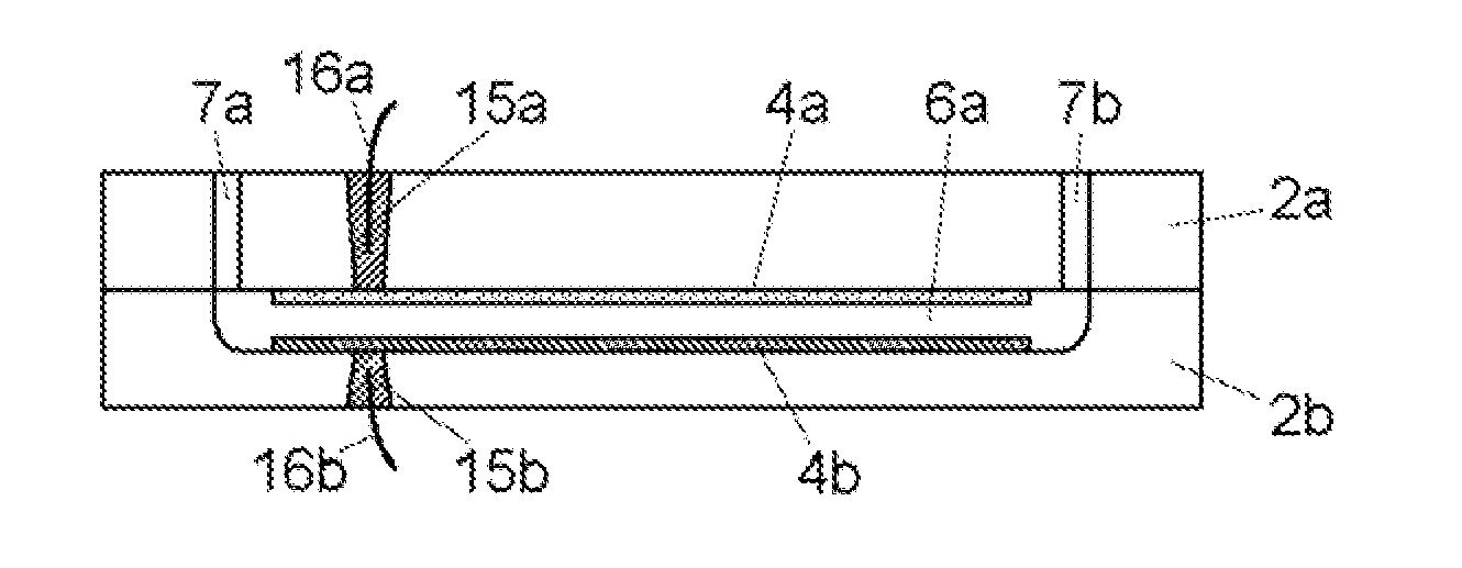
[0056]A flowcell 2 is constructed by bonding two sheets of insulating substrates 2a and 2b, and a channel 6 is formed in the inside thereof. The flowcell 2 is provided with a pair of electrodes 4a and 4b that are disposed in parallel to oppose each other within the channel 6. The electrodes 4a and 4b are firmly fixed to the substrates 2a and 2h, respectively, The flowcell 2 is mourned on a temperature adjusting unit 11. One end of the channel 6 is a liquid introducing inlet that is connected to a liquid feeding unit 8 constructed, for example, of a syringe pump. The other end of the channel 6 is a drain for discharging the liquid that has flowed through the channel 6 to the outside of the flowcell 2.

[0057]The liquid feeding unit 8 is adapted to be capable of suitably switching the liquid to be supplied or to be capable of being converted to liquid feeding u...


PUM

PropertyMeasurementUnit
distanceaaaaaaaaaa
depthaaaaaaaaaa
temperatureaaaaaaaaaa

Abstract

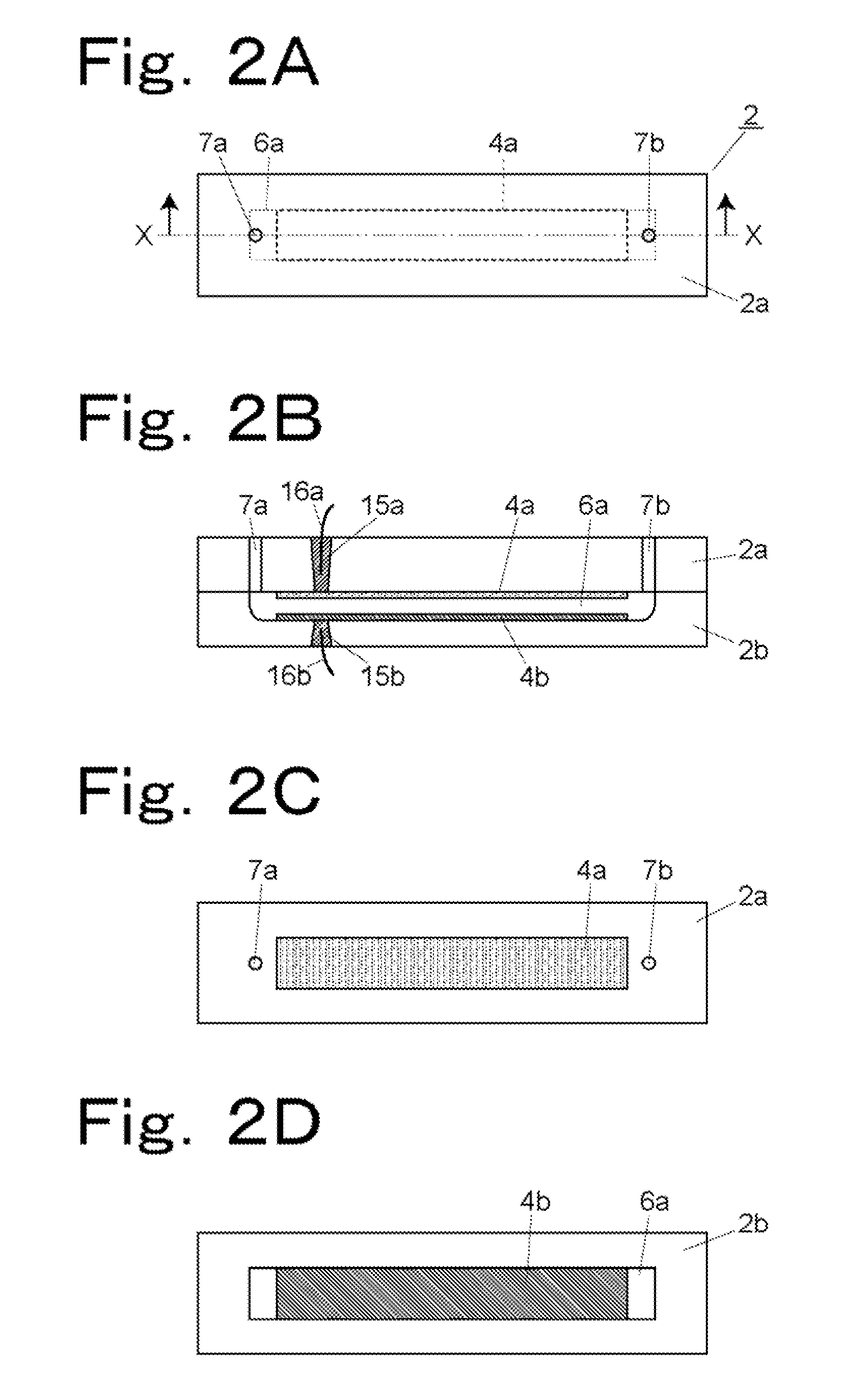
A flowcell 2 is constituted of insulating substrates 2a and 2b. The two substrates 2a and 2b have been directly bonded to each other by a bonding method for attaining tenacious bonding, for example, anodic bonding or hydrofluoric acid bonding. A channel 6 has been formed at the interface between the substrates 2a and 2b. Part of the substrate 2a which faces the channel 6 has a carbon electrode 4a formed thereon by sintering a pasty carbon material, the electrode 4a extending along the channel 6. On the other hand, the substrate 2b has a groove 6a serving as the channel 6, and has an electrode 4b made of a metal film formed on a bottom surface of the groove 6a.

Description

TECHNICAL FIELD[0001]The present invention relates to a technical field in which an 18F− ion obtained by radiating a proton accelerated by a cyclotron to [18O]—H2O water is separated from the [18O]—H2O water so as to produce an organic solvent solution of the 18F− ion, and in particular to a flowcell used for that purpose, a radioactive fluoride anion concentrating apparatus provided with the flowcell, and a radioactive fluoride anion concentrating method using the apparatus.BACKGROUND ART[0002]Among the medical diagnosis methods using radioactive tracer compounds, many of the radioactive nuclides used in a PET (Positron Emission Tomography) diagnosis have a short half-life and, for example, the half-life of an 18F− ion is about 110 minutes. In order to introduce these radioactive nuclides efficiently into tracer compounds to make the compounds radioactive, a time-saving work will be needed.[0003]Also, since [18O]—H2O water serving as a source material of the 18F− ion is expensive, ...

Claims


Application Information

Patent Timeline
Patent Type & Authority Patents(United States)
IPC IPC(8): G01N30/00G01N30/88G01N30/26
CPCB01D59/42G21G1/001G21G4/00Y10T156/10G21G2001/0015
Inventor NAKANISHI, HIROAKIKONISHINAKA, KEISUKE
Owner SHIMADZU CORP
Learn More