Method and system for providing an NFT using a sacrificial NFT structure

a technology of nft and sacrificial nft, which is applied in the field of providing an nft using a sacrificial nft structure, can solve the problems of low yield and/or higher variations of the underlying waveguide of the conventional nft, and achieve the effect of reducing the cost of production

Active Publication Date: 2013-07-23
WESTERN DIGITAL TECH INC
View PDF10 Cites 160 Cited by
  • Summary
  • Abstract
  • Description
  • Claims
  • Application Information

AI Technical Summary

Problems solved by technology

In particular, fabrication of the conventional NFT 30 may have low yield and/or higher var...

Method used


Image

  • Method and system for providing an NFT using a sacrificial NFT structure
  • Method and system for providing an NFT using a sacrificial NFT structure
  • Method and system for providing an NFT using a sacrificial NFT structure

Examples


Embodiment Construction

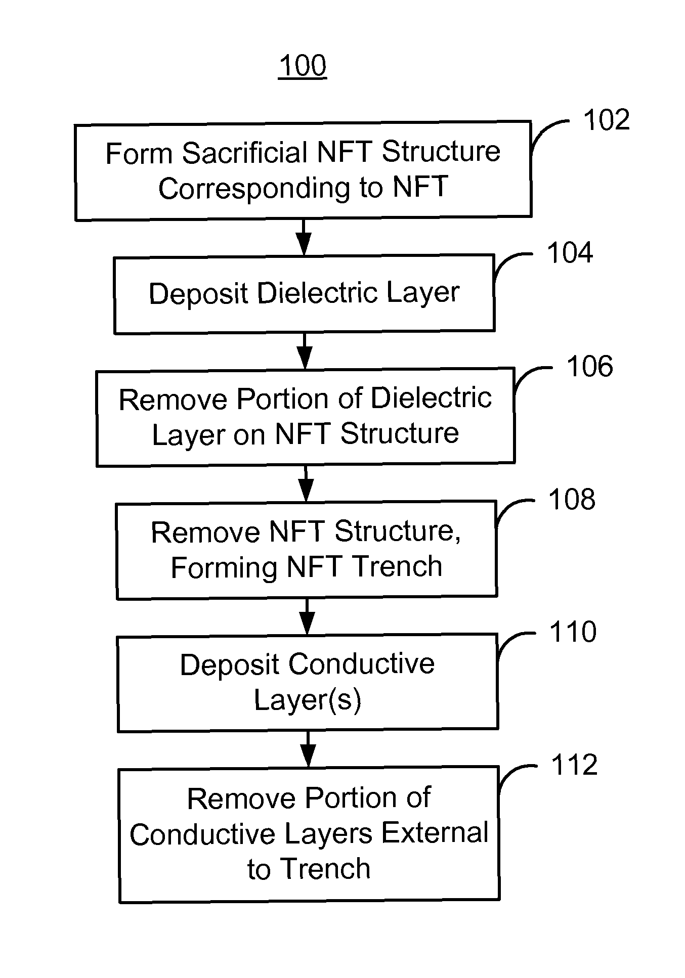
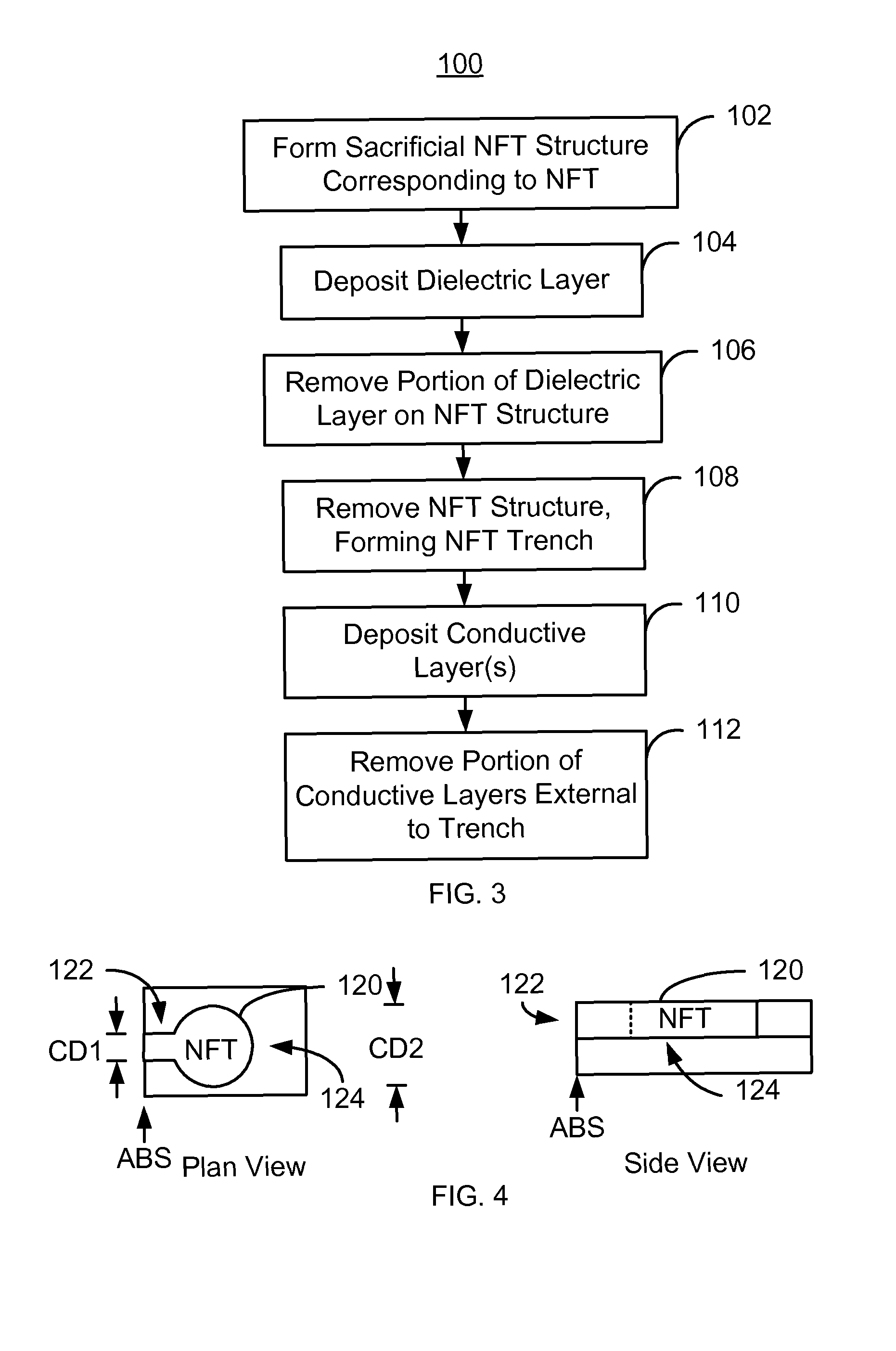
[0013]FIG. 3 depicts one embodiment of a method 100 for fabricating an NFT for an EAMR transducer. For simplicity, some steps may be omitted, interleaved, and / or combined. The EAMR transducer being fabricated may be part of a merged head that also includes a read head and resides on a slider in a disk drive. The method 100 is also described in the context of providing a single EAMR transducer. However, the method 100 may be used to fabricate multiple transducers at substantially the same time. The method 100 is also described in the context of particular layers. However, in some embodiments, such layers may include multiple sub-layers. The method 100 also may commence after formation of other portions of the EAMR transducer. In one embodiment, the method 100 commences after formation of portions of the waveguide, such as a core. Thus, a flat surface for formation of subsequent structures may have been provided. Certain steps of the method 100 may be combined, omitted, performed in a...


PUM

PropertyMeasurementUnit
Angleaaaaaaaaaa
Dielectric polarization enthalpyaaaaaaaaaa
Shapeaaaaaaaaaa

Abstract

A method and system provides a near-field transducer (NFT) for an energy assisted magnetic recording (EAMR) transducer. The method and system include forming a sacrificial NFT structure having a shape a location corresponding to the NFT. A dielectric layer is deposited. A portion of the dielectric layer resides on the sacrificial NFT structure. At least this portion of the dielectric layer on the sacrificial structure is removed. The sacrificial NFT structure is removed, exposing an NFT trench in the dielectric layer. At least one conductive layer for the NFT is deposited. A first portion of the conductive layer(s) reside in the NFT trench. A second portion of the conductive layer(s) external to the NFT trench is removed to form the NFT.

Description

BACKGROUND[0001]FIG. 1 depicts a portion of a conventional energy assisted magnetic recording (EAMR) transducer 10. The conventional EAMR transducer 10 includes a conventional waveguide 12 having a conventional core 18 and cladding 14 and 16, a grating 20, a conventional near-field transducer (NFT) 30, and a write pole 40. The NFT 30 has a disk portion 34 and a pin portion 32. The pin portion 32 is between the disk portion 34 and the air-bearing surface (ABS). The conventional EAMR transducer 10 is used in writing to a recording media and receives light, or energy, from a conventional laser (not shown). In operation, light from a laser is coupled to the waveguide 12. Light is guided by the conventional waveguide 12 to the NFT 30 near the ABS. The NFT 30 utilizes local resonances in surface plasmons to focus the light to magnetic recording media (not shown), such as a disk. The surface plasmons used by the NFT 30 are electromagnetic waves that propagate along metal / dielectric interfa...

Claims


Application Information

Patent Timeline
IPC IPC(8): B44C1/22G11B5/127
CPCG11B5/3133G11B5/6088Y10T29/49032Y10T29/49048G11B2005/0021
Inventor TANNER, SHAWN M.HU, YUFENGTRAN, UTWANG, ZHONGYAN
Owner WESTERN DIGITAL TECH INC
Why Eureka
Try Eureka