Method for starting a gas-phase oxidation reactor

Active Publication Date: 2013-07-23
BASF SE
View PDF39 Cites 1 Cited by
  • Summary
  • Abstract
  • Description
  • Claims
  • Application Information

AI Technical Summary

Benefits of technology

[0011]It is an object of the invention to specify a process for starting up the gas phase oxidation reactor which combines a short start

Problems solved by technology

These “hotspots” cause side reactions, such as the total combustion of the starting material, or lead to the formation of undesirable by-products which can be removed from the reaction product only with a high level of complexity, if at all, for example phthalide or benzoic acid.
However, the formation of a marked hotspot prevents a rapid startup phase, since, from a

Method used


Image

  • Method for starting a gas-phase oxidation reactor
  • Method for starting a gas-phase oxidation reactor
  • Method for starting a gas-phase oxidation reactor

Examples


Example

[0096]The comparative example was repeated, except that, after 60 cm of the layer of catalyst 1, a 10 cm catalytically inactive layer of steatite rings (external diameter 7 mm, height 4 mm, internal diameter 4 mm, with two notches on the end faces) was introduced as a moderator layer. This gave rise to the following bed length distribution: 60 / 10 / 60 / 50 / 70 / 70 cm (catalyst 1a / moderator layer / catalyst 1b / catalyst 2 / catalyst 3 / catalyst 4).

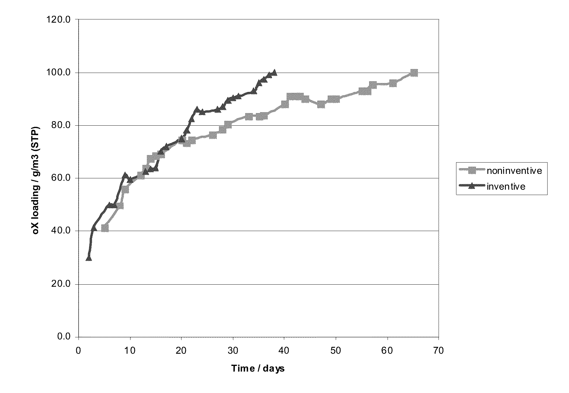
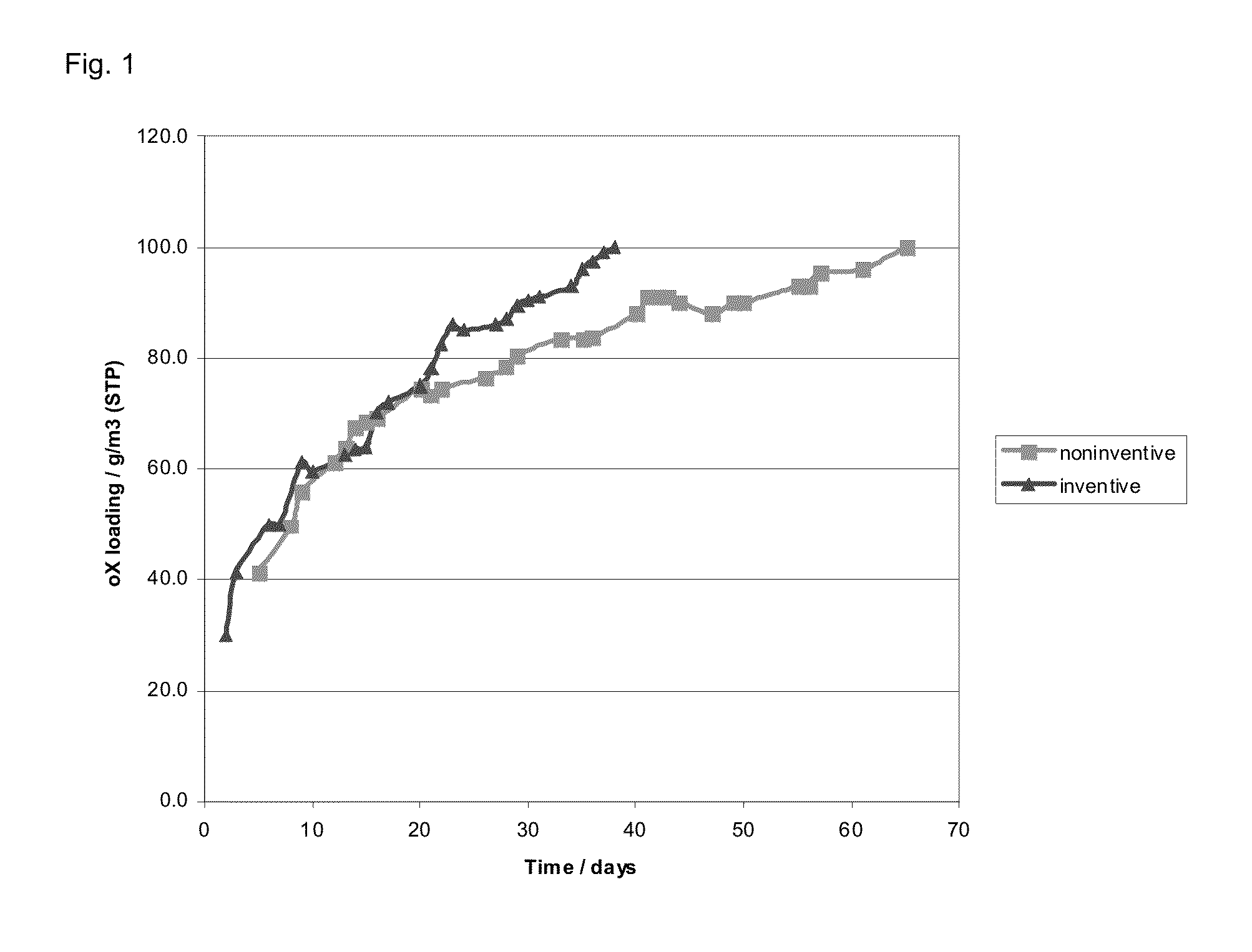
[0097]The loading of the air stream with o-xylene was increased from 30 g / m3 (STP) to 100 g / m3 (STP) over the course of 40 days, as shown by the triangular symbols in FIG. 1. At the same time, the salt bath temperature was lowered from 390° C. to 353° C., as shown by the triangular symbols in FIG. 3.

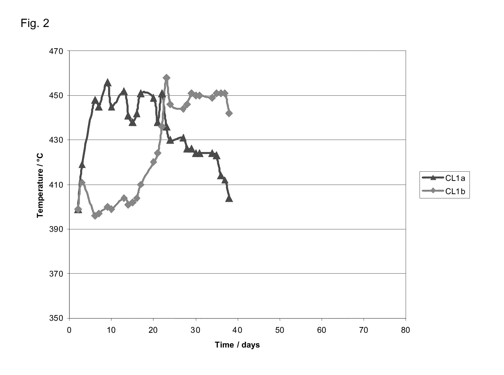
[0098]FIG. 2 shows the plot of the hotspot temperature in the bed of catalyst 1 disposed upstream of the moderator layer (CL1a) and of the bed of catalyst 1 disposed downstream of the moderator layer (CL1b). At first, a hotspot forms in the region of bed CL...


PUM


Abstract

What is described is a process for starting up a gas phase oxidation reactor for oxidation of o-xylene to phthalic anhydride, said reactor comprising at least one catalyst layer and being temperature-controllable by means of a heat carrier medium, wherein a) the catalyst layer is interrupted by a moderator layer which is less catalytically active than the catalyst layer or is catalytically inactive, b) a gas stream is passed through the reactor with an initial loading of o-xylene and at an initial temperature of the heat transfer medium, c) the loading of the gas stream is increased to a target loading and, in parallel, the temperature of the heat transfer medium is lowered to an operating temperature. The introduction of the moderator layer allows the loading to be increased more rapidly and the startup time to be shortened.

Description

CROSS-REFERENCE TO RELATED APPLICATIONS[0001]This application is a national stage application (under 35 U.S.C. §371) of PCT / EP2009 / 054168, filed Apr. 7, 2009 which claims benefit of European application 08154169.0, filed Apr. 7, 2008.BACKGROUND OF THE INVENTION[0002]The invention relates to the preparation of phthalic anhydride by gas phase oxidation of o-xylene. To this end, a gas stream which comprises molecular oxygen and o-xylene is generally passed through a multitude of tubes disposed in a reactor, in which a bed of at least one catalyst is present. To regulate the temperature, the tubes are surrounded by a heat carrier medium, for example a salt melt.[0003]In spite of this thermostating, so-called “hotspots” form in the catalyst bed, at which the temperature is higher than in the remainder of the catalyst bed. These “hotspots” cause side reactions, such as the total combustion of the starting material, or lead to the formation of undesirable by-products which can be removed f...

Claims


Application Information

Patent Timeline
IPC IPC(8): C07D307/89
CPCC07D307/89C07C51/265
Inventor WILMER, HAGENZUHLKE, JURGENLAUTENSACK, THOMASALLMANN, HANS-MARTINROSOWSKI, FRANKDOBNER, CORNELIA KATHARINA
Owner BASF SE
Why Eureka
Try Eureka