Subsea compression system and method

Inactive Publication Date: 2010-10-26
KVAERNER OILFIELD PROD AS
View PDF19 Cites 15 Cited by
  • Summary
  • Abstract
  • Description
  • Claims
  • Application Information

AI Technical Summary

Benefits of technology

[0028]Magnetic bearings, i.e. no oil lubrication system, allows the shortest possible start up time of a subsea compressor, because there is no lube oil that needs to be heated up to lube oil running temperature. Further, because the temperature of the inlet gas from the scrubber is at or close to seawater temperature, the recirculation of gas through the recirculation line (anti-surge line) should be kept to a minimum, i.e. only to bring the compressor disch

Problems solved by technology

Such throttling will however be modest, typically a fraction of 1 bar.
There are several disadvantages by subsea separation at higher temperatures than seawater temperatures:The necessary compression power will always be higher compared to compression

Method used


Image

  • Subsea compression system and method
  • Subsea compression system and method
  • Subsea compression system and method

Examples


Example

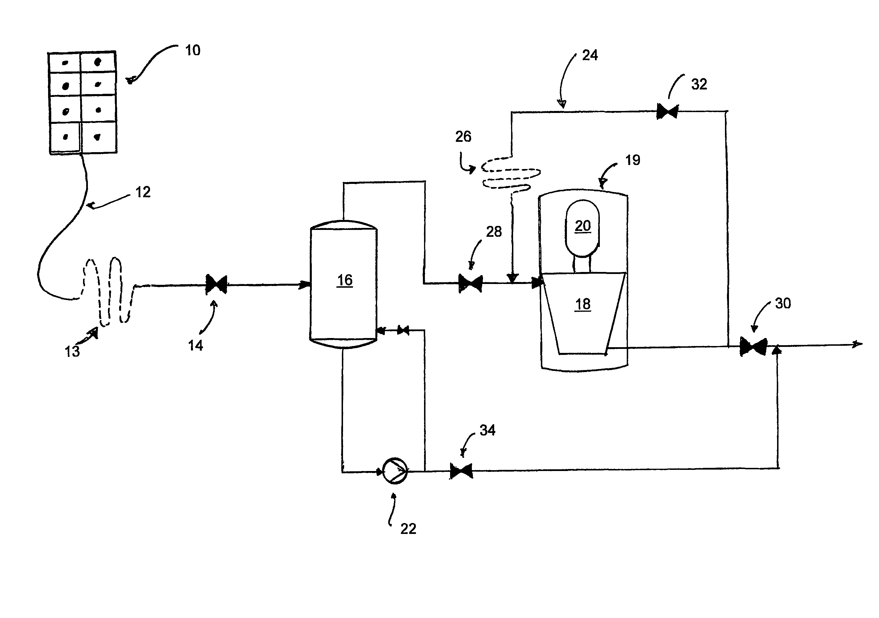
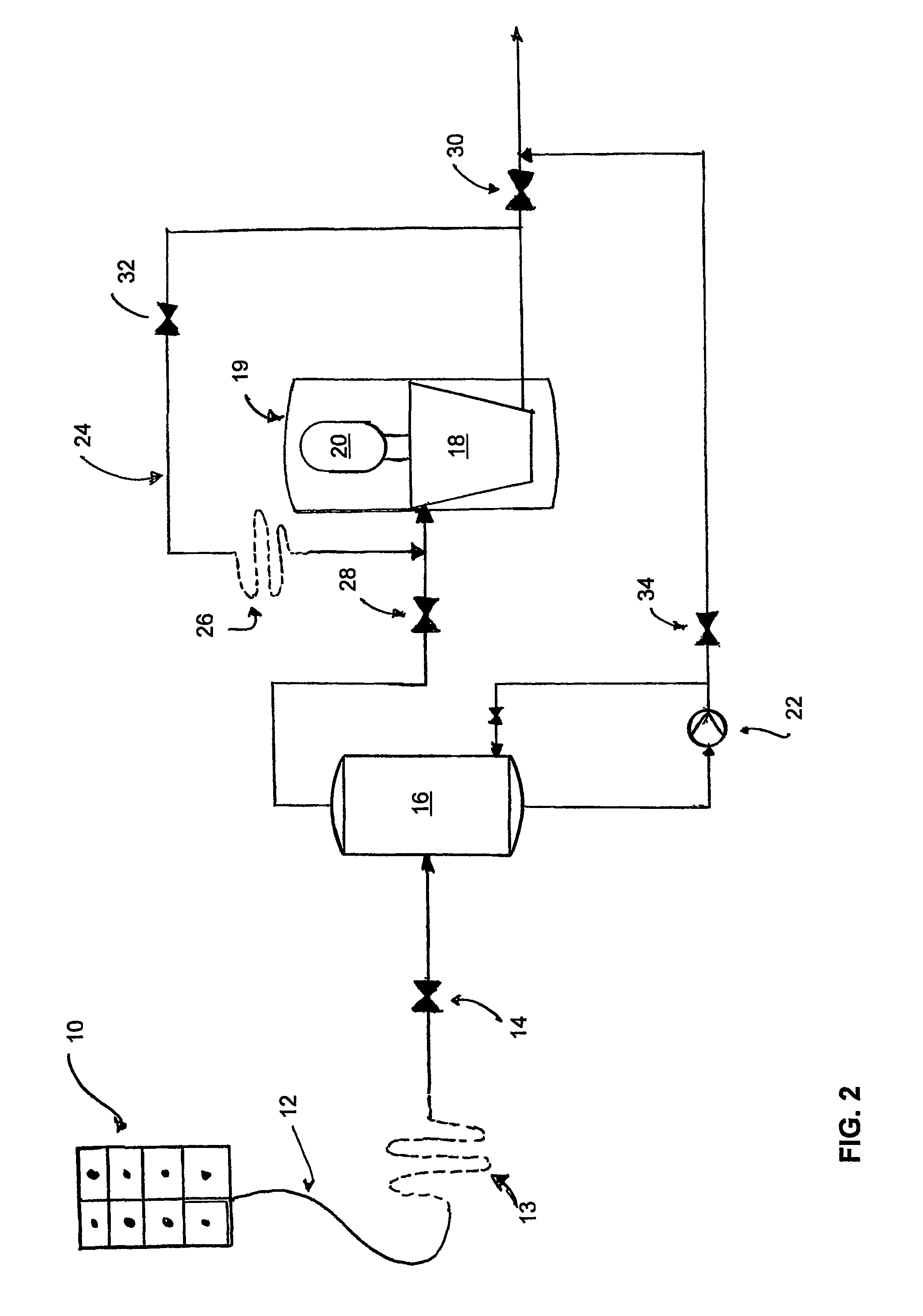
[0037]Referring to FIG. 2, which illustrates one aspect of the invention, a subsea template or manifold 10 is schematically illustrated. The manifold may comprise a number of slots as well as a hydrate inhibitor injection unit, for injecting e.g. MEG or methanol into the well stream. The well stream is flowed in the flow line 12 to the subsea compression system. It is a basic requirement for the invention that the well stream is inhibited against the formation of hydrates as described, at a location upstream of the compression system, and before the well stream is being cooled down to a temperature at which hydrate formation may occur (typically about 25° C.). The injection of hydrate inhibitants also ensures that hydrates do not form along the flow lines to the distant onshore or offshore receiving facility.

[0038]By virtue of the long flow line 12 (e.g. 2 to 3 km) the well stream is cooled to a temperature that is equal to, or in the region of, the surrounding sea water temperature...


PUM

PropertyMeasurementUnit
Temperatureaaaaaaaaaa
Lengthaaaaaaaaaa

Abstract

A subsea compression system and method wherein a wellstream fluid is flowed through a flow line (12) from a reservoir (10) and into a separation vessel (16) for subsequent compression in a compressor (18; 18′, 18″) prior to export of gas. A recycle line (24; 24′, 24″) is fluidly connected at a first end to the compressed wellstream at the outlet side of the compressor (18; 18′, 18″) and at a second end to the wellstream at a location between the separation vessel (16) and the inlet side of the compressor (18; 18′, 18″), the recycle line being capable of controllably (32) feeding fluid due to surge back to the compressor inlet side and avoiding the need to feed the fluid into the separation vessel, because the re-circulated gas is dry both due to having been separated at seawater temperature, and then being heated during recirculation.

Description

BACKGROUND OF THE INVENTION[0001]The present invention relates to subsea gas compression.[0002]More specifically the invention relates to a system and method for cooling a well stream down to, or in the region of, the temperature of the surrounding seawater, prior to the well stream gas entering the scrubber. More specifically, the invention relates to a system and method wherein a well stream fluid is flowed through a flow line from a reservoir and into a separation vessel for subsequent compression of the separated gas stream in a compressor prior to export of gas.DESCRIPTION OF THE RELATED ART[0003]It could seem desirable to endeavour to keep the separation temperature in the separator / scrubber of a subsea compression station and the temperature of the gas leaving the scrubber, above hydrate temperature, approximately 25° C. or more, to avoid hydrate formation. Typical for topsides and onshore is to insulate and trace heat the pipe between the scrubber and the compressor inlet to...

Claims


Application Information

Patent Timeline
IPC IPC(8): B01D47/00E21B43/01E21B43/36
CPCE21B43/01E21B43/36
Inventor STINESSEN, KJELL OLAVSKOFTELAND, HAKON
Owner KVAERNER OILFIELD PROD AS
Why Eureka
Try Eureka