Temporal thermal imaging method for detecting subsurface objects and voids

a technology of subsurface objects and thermal imaging, applied in the field of temporal thermal imaging methods for detecting subsurface objects and voids, can solve the problems of emissivity-related noise, typically 1 or 2 degree ° c., and the conventional single-band thermal imaging is difficult to interpret, so as to achieve the effect of effectively removing background clutter and enhancing the detection of thermal inertia outliers

Active Publication Date: 2013-07-23
DEL GRANDE NANCY KERR
View PDF6 Cites 18 Cited by
  • Summary
  • Abstract
  • Description
  • Claims
  • Application Information

AI Technical Summary

Benefits of technology

[0029](1) Optimizing thermal survey times to enhance detection of object sites.
[0033](1) enhances surface temperature differences versus time to locate tunnels or object-voids at depth; maps heat flows from naturally-heated voids at depths 2-20 times their heights;
[0035](4) removes clutter from foreign objects and non-thermal (reflected or absorbed) signals;
[0038](7) Distinguishes safe from hazardous locations which may contain explosive devices or support “at risk” structures e.g., corroded bridge decks or natural gas transmission lines.
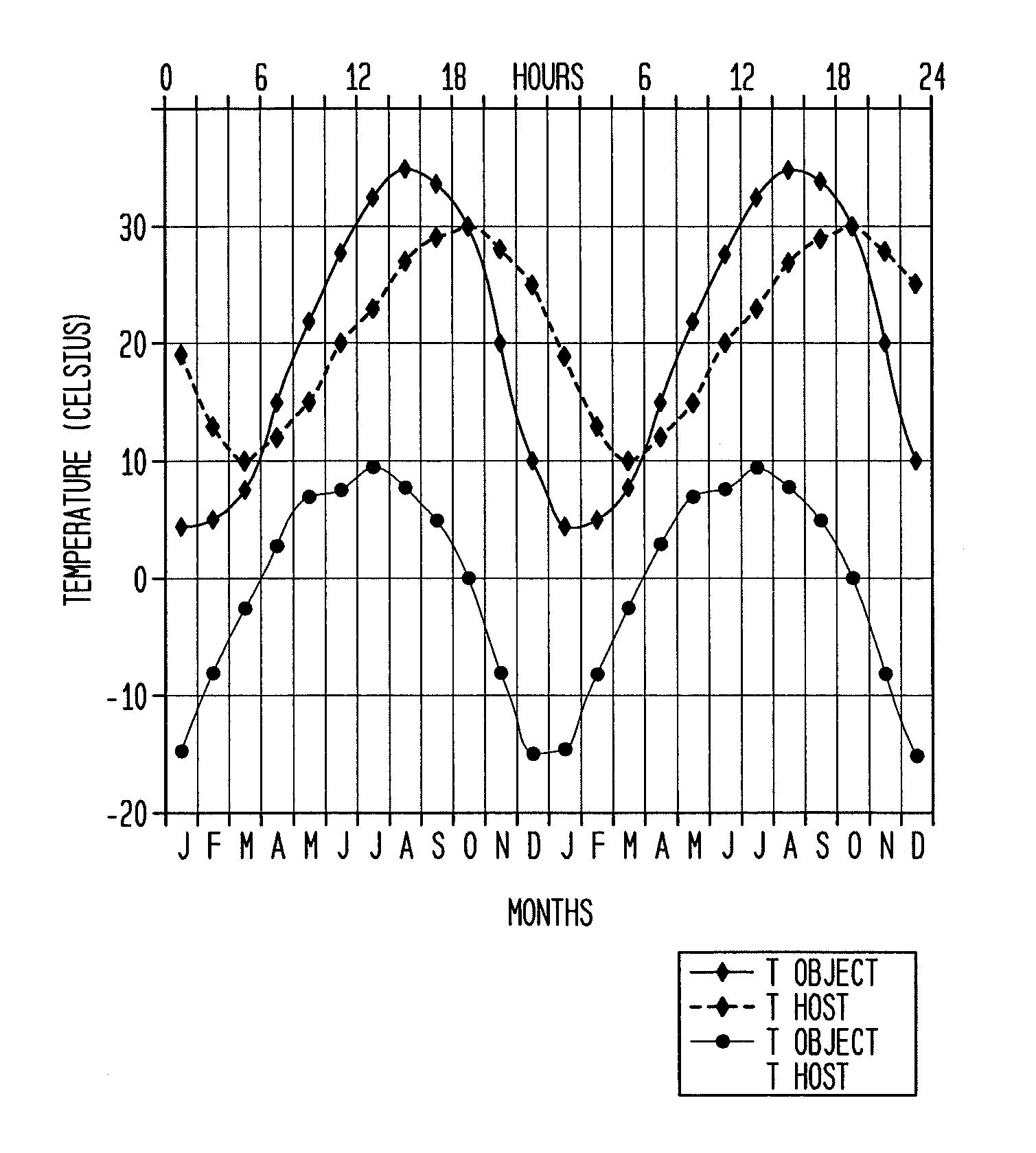
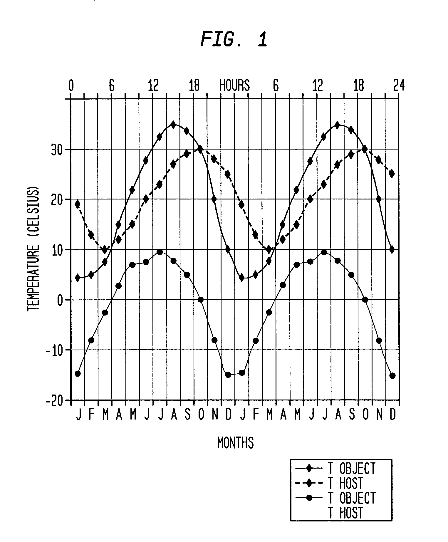
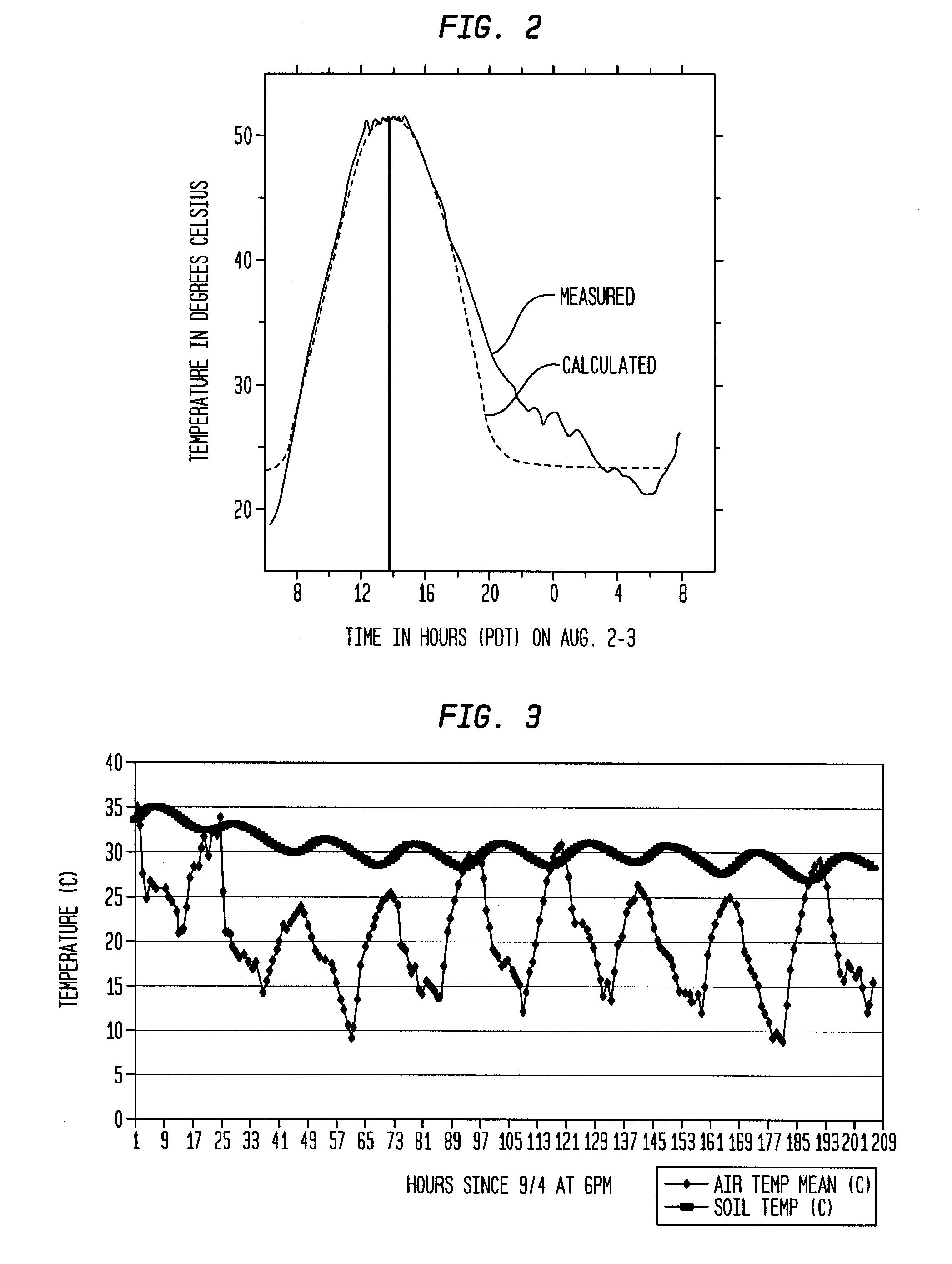
[0039]An alternative approach to using an Annual Surface Climate Energy Budget (ASCEB) model described in U.S. Pat. No. 7,157,714 is to map air and host material temporal thermal changes which distinguish object sites from normal, undisturbed host material sites. Realistic input parameters are provided using the DIRECT method as an empirical approach to locate and characterize the depth and dimensions of object sites. This is used to enhance detection of thermal inertia outliers at the borders of object sites.
[0040]An automated airborne temporal thermal survey method, applicable to any area of the world, is described in accordance with the present invention to detect the presence of buried objects and indicate general information about the size, type and depth of the object. The approach takes advantage of heating and cooling rate differences between background materials and the location that contains buried objects. The method uses dual (mid-wave IR and long-wave IR) thermal imagery and a modeling approach to determine the highest probability of detecting objects of a particular size and at a particular depth. The approach highlights thermal contrast at the locations of buried objects. It uses dual bands to provide the ability to determine temperature and emissivity independently, effectively removing background clutter.

Problems solved by technology

However, the conventional single band thermal imaging is difficult to interpret.
These conventional single band imaging techniques fail to distinguish between surface emissivity clutter and true temperatures.
In addition, emissivity-related noise, typically 1 or 2 degree ° C., cannot be removed using a single passive thermal IR band even when used in conjunction with another active laser reflectance IR band.

Method used


Image

  • Temporal thermal imaging method for detecting subsurface objects and voids
  • Temporal thermal imaging method for detecting subsurface objects and voids
  • Temporal thermal imaging method for detecting subsurface objects and voids

Examples


Embodiment Construction

[0062]In describing the preferred embodiments of the invention illustrated in the drawings, specific terminology will be used for the sake of clarity. However, the invention is not intended to be limited to the specific terms so selected, and it is to be understood that each specific term includes all technical equivalents that operate in a similar manner to accomplish a similar purpose.

[0063]Thermal inertia (effusivity) change detection can be used to find less solid and less dense underground object locations, such as subsurface explosive devices, underground tunnels and caves, and other structures and sites such as underground pipes, or other objects, i.e., an artifact amidst clutter and the surrounding host materials such as natural earth materials, paved roads or bodies of water. It can also be used to locate and quantify the size and extent of delaminations within paved bridges, highways and landing strips and material-loss thinning within coated or covered pipelines and aircr...


PUM

PropertyMeasurementUnit
wavelengthaaaaaaaaaa
apparent temperatureaaaaaaaaaa

Abstract

A temporal thermal survey method to locate at a given area whether or not there is a subsurface object or void site. The method uses thermal inertia change detection. It locates temporal heat flows from naturally heated subsurface objects or faulty structures such as corrosion damage. The added value over earlier methods is the use of empirical methods to specify the optimum times for locating subsurface objects or voids amidst clutter and undisturbed host materials. Thermal inertia, or thermal effusivity, is the bulk material resistance to temperature change. Surface temperature highs and lows are shifted in time at the subsurface object or void site relative to the undisturbed host material sites. The Dual-band Infra-Red Effusivity Computed Tomography (DIRECT) method verifies the optimum two times to detect thermal inertia outliers at the subsurface object or void border with undisturbed host materials.

Description

CROSS-REFERENCE TO RELATED APPLICATIONS[0001]This application claims the benefit of the filing dates of U.S. Provisional Patent Application Nos. 61 / 393,597, filed Oct. 15, 2010, entitled “Temporal Thermal Survey Method To Locate Subsurface Explosive Devices And Underground Tunnels”; 61 / 342,369, filed Apr. 13, 2010, entitled “Temporal Thermal Survey Method To Locate Subsurface Objects Or Voids”; 61 / 342,184, filed Apr. 9, 2010, entitled “Temporal Thermal Survey Method To Locate Underground Tunnels And Caves”; 61 / 341,932, filed Apr. 7, 2010, entitled “Temporal Thermal Survey Method To Locate Subsurface Explosive Devices”; and 61 / 337,716, filed Feb. 9, 2010, entitled “Temporal Method To Locate Buried Objects,” the disclosures of which are hereby incorporated herein by reference.BACKGROUND OF THE INVENTION[0002]The present invention by incorporating temporal thermal imaging using dual band infrared (IR) wavelengths enables locating underground objects such as subsurface explosive devices...

Claims


Application Information

Patent Timeline
Patent Type & Authority Patents(United States)
IPC IPC(8): G06K9/00G06V20/13
CPCG01K11/00G06K9/0063G06V20/13
Inventor DEL GRANDE, NANCY KERR
Owner DEL GRANDE NANCY KERR
Why Eureka
Try Eureka