All row, planar fault detection system

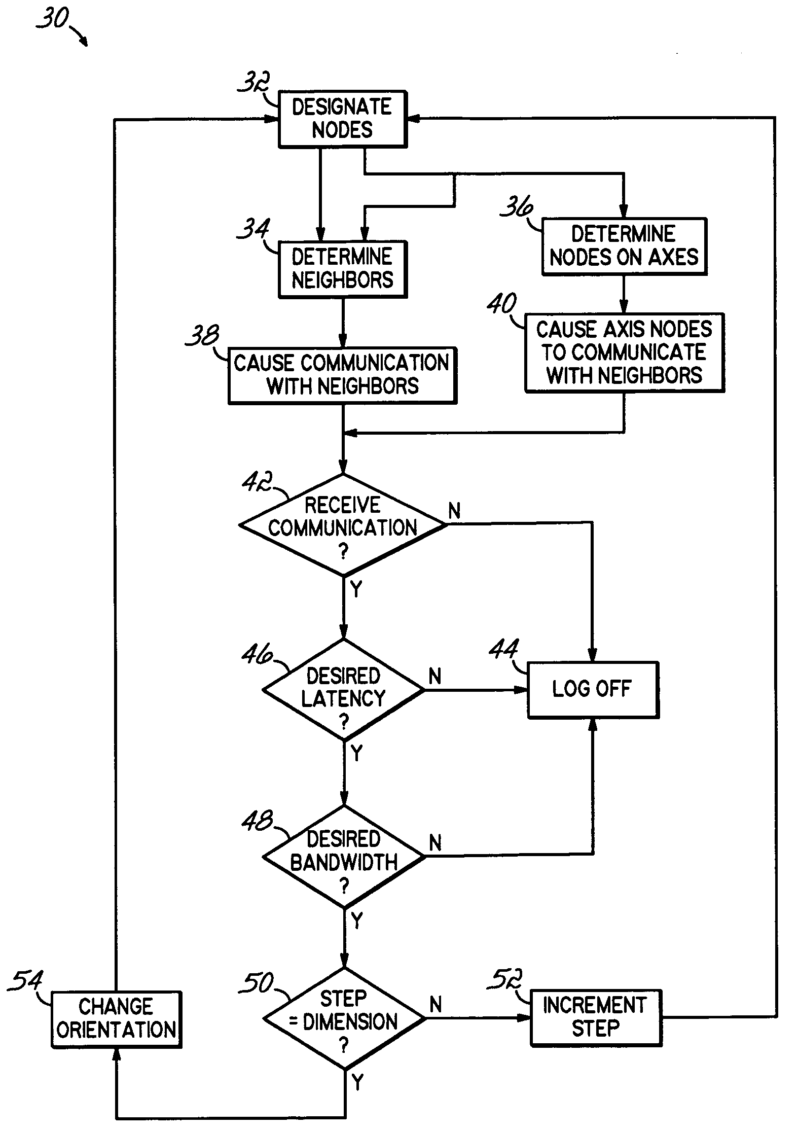
a fault detection and all row technology, applied in error detection/correction, digital computers, instruments, etc., can solve problems such as difficult to pinpoint the address, or even the general region of a node, and hinder the performance of the aggregate, so as to quickly evaluate all nodes and links, the effect of minimizing the concentration of links during a given time step

Inactive Publication Date: 2013-07-23
INT BUSINESS MASCH CORP
View PDF33 Cites 0 Cited by
  • Summary
  • Abstract
  • Description
  • Claims
  • Application Information

AI Technical Summary

Benefits of technology

[0012]Aspects of the present invention may designate one or nodes in the cell in such a manner as contention for links during a given time step is minimized. During a subsequent time step, new nodes may designated and coordinated such that competition for common links remains minimal or non existent. Such features, which may also include rotating the dimensions of planes used to evaluate nodes, may relatively quickly evaluate all nodes and links without undesirably burdening system processors or memory.

Problems solved by technology

Despite the improved fault tolerance afforded by parallel computing systems, however, faulty nodes can hinder performance in the aggregate.
The relatively large number of nodes used in some such systems, however, can complicate node maintenance.
With so many nodes and alternative data paths, it may be difficult to pinpoint the address, or even the general region of a node, or nodal connection requiring service.

Method used


Image

  • All row, planar fault detection system
  • All row, planar fault detection system
  • All row, planar fault detection system

Examples


Embodiment Construction

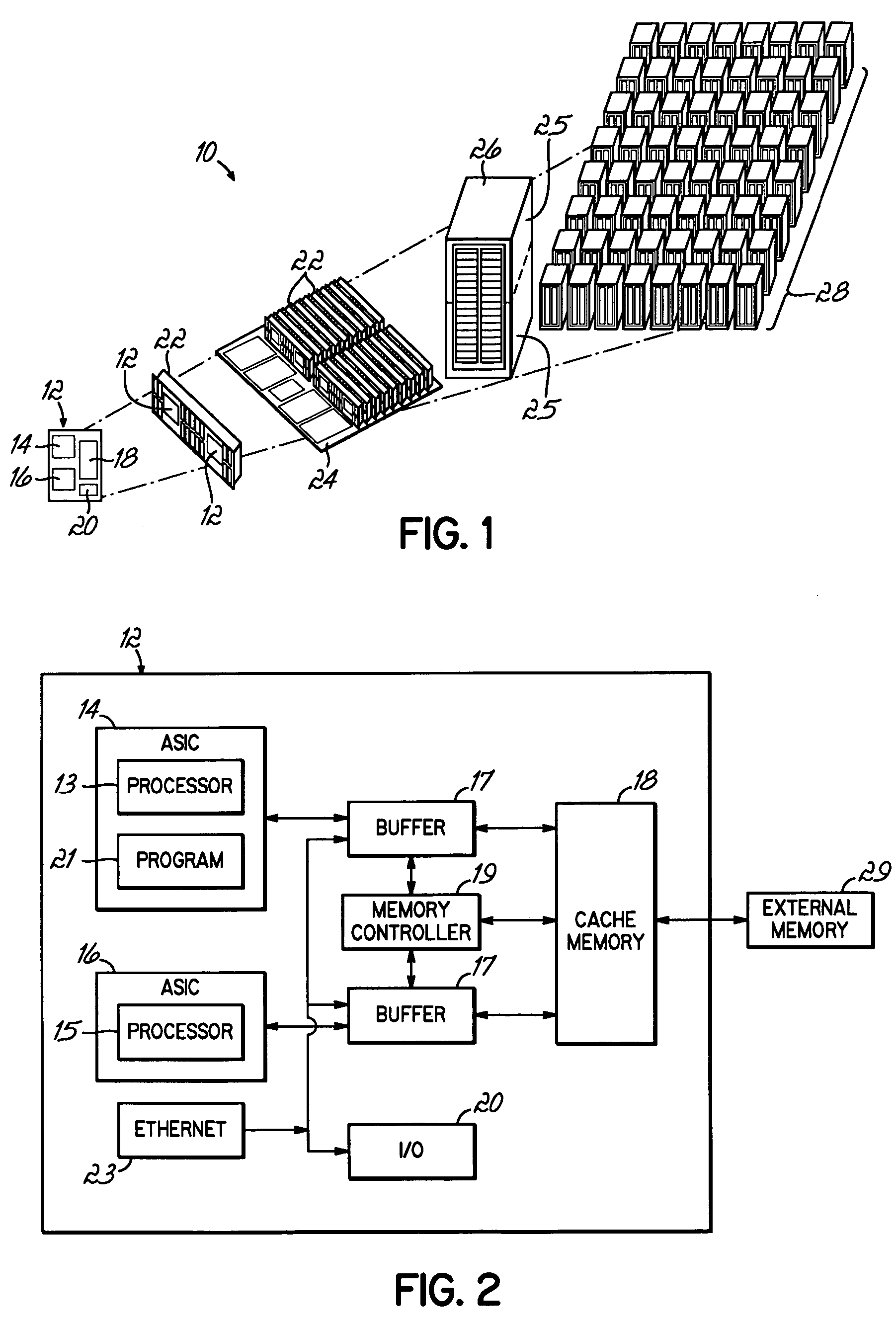
[0019]Parallel computing systems, such as the BlueGene / L system created by International Business Machines, often include a node cellular architecture. As discuss below in detail, the BlueGene / L system is built from blocks of node midplanes that may be connected through several inter and intra midplane networks. The system may be constructed incrementally, with midplane cells being added to build the larger, final system. As each midplane is added to the system, the hardware and system software must be tested for faulty configurations, including interconnect, processing, memory and software control.

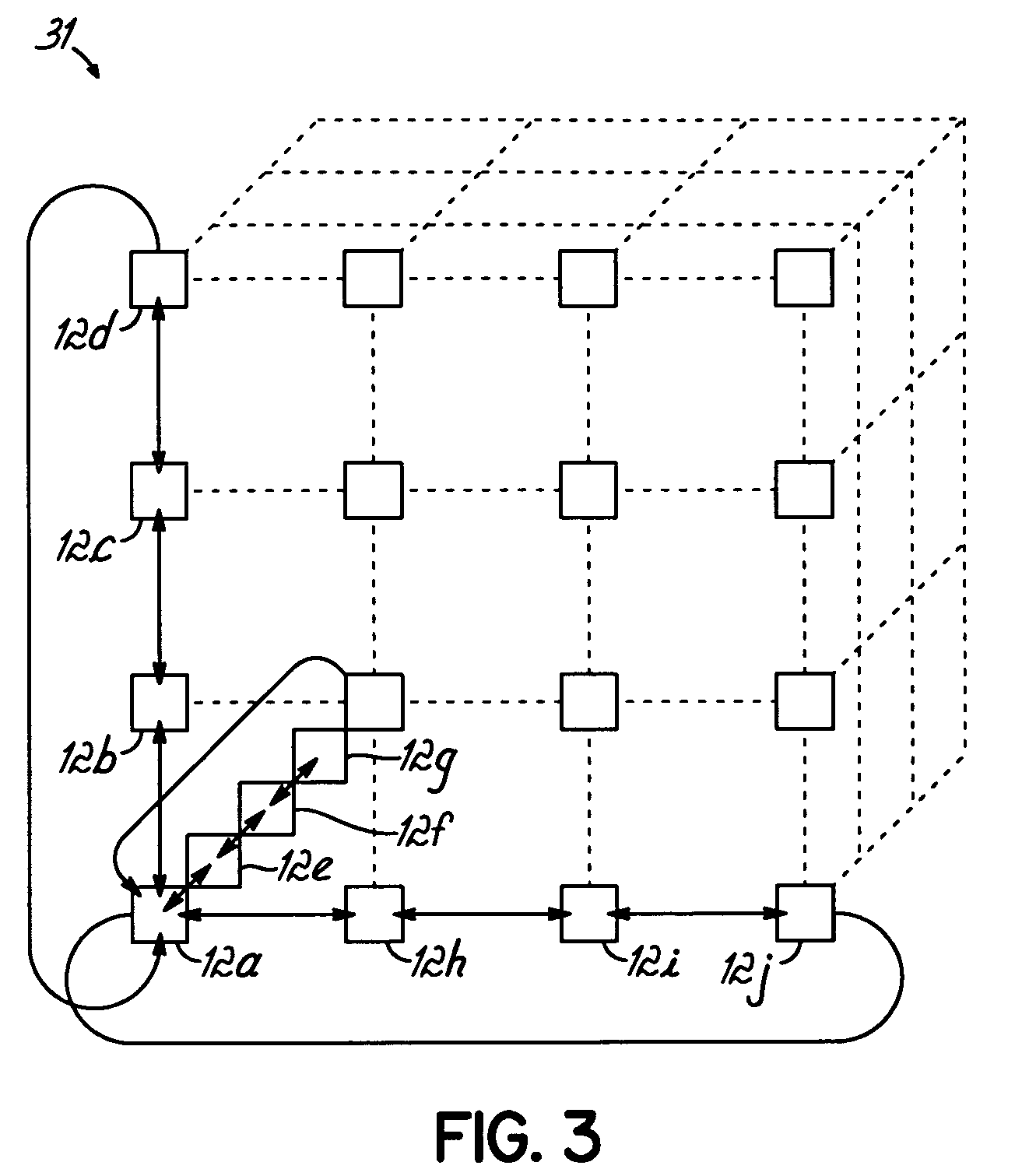
[0020]The primary point to point message passing network for BlueGene / L is a three dimensional torus network, where every node is connected to six other nodes in a mesh, forming a cube of (x,y,z) nodes. For example, a 512 node midplane torus consists of an 8×8×8 node arrangement. Torus implies that the nodes on the face of the cube wrap around to connect to nodes on the opposite face. Thi...


PUM


Abstract

An apparatus, program product and method for detecting nodal faults may simultaneously cause designated nodes of a cell to communicate with all nodes adjacent to each of the designated nodes. Furthermore, all nodes along the axes of the designated nodes are made to communicate with their adjacent nodes, and the communications are analyzed to determine if a node or connection is faulty.

Description

[0001]This invention was made with Government support under Contract No. B519700 awarded by the Department of Energy. The Government has certain rights in this invention.CROSS-REFERENCE TO RELATED APPLICATIONS[0002]This application is related to the following U.S. patent applications all filed on even date herewith by Charles Jens Archer et al.: Ser. No. 11 / 052,658, entitled “ALL-TO-ALL SEQUENCED FAULT DETECTION SYSTEM,” Ser. No. 11 / 052,659, entitled “CELL BOUNDARY FAULT DETECTION SYSTEM,” Ser. No. 11 / 052,660, entitled “ROW FAULT DETECTION SYSTEM,” Ser. No. 11 / 052,661, entitled “MULTI-DIRECTIONAL FAULT DETECTION SYSTEM,” and Ser. No. 11 / 052,663, entitled “BISECTIONAL FAULT DETECTION SYSTEM,”. The present application is also related to U.S. patent application filed on even date herewith by John A. Gunnels et al., Ser. No. 11 / 050,945, entitled “SYSTEM AND METHOD FOR DETECTING A FAULTY OBJECT IN A SYSTEM,”. Each of these applications is incorporated by reference herein.FIELD OF THE INV...

Claims


Application Information

Patent Timeline
Patent Type & Authority Patents(United States)
IPC IPC(8): G06F11/00
CPCG06F11/0724G06F11/079G06F11/2035
Inventor ARCHER, CHARLES JENSPINNOW, KURT WALTERRATTERMAN, JOSEPH D.SMITH, BRIAN EDWARD
Owner INT BUSINESS MASCH CORP
Why Eureka
Try Eureka