Shaping tool having a rotatable base member

a technology of rotatable base and tool, which is applied in the direction of forging/pressing/hammering apparatus, single-unit apparatus, forging presses, etc., can solve the problems of non-gastight end contour, defect, etc., and achieve the effect of reliable operation

Active Publication Date: 2013-07-30
BOEHRINGER INGELHEIM INT GMBH
View PDF16 Cites 26 Cited by
  • Summary
  • Abstract
  • Description
  • Claims
  • Application Information

AI Technical Summary

Benefits of technology

[0004]The problem that the invention sets out to solve is to provide a shaping tool of the kind mentioned hereinbefore which is reliable in operation.
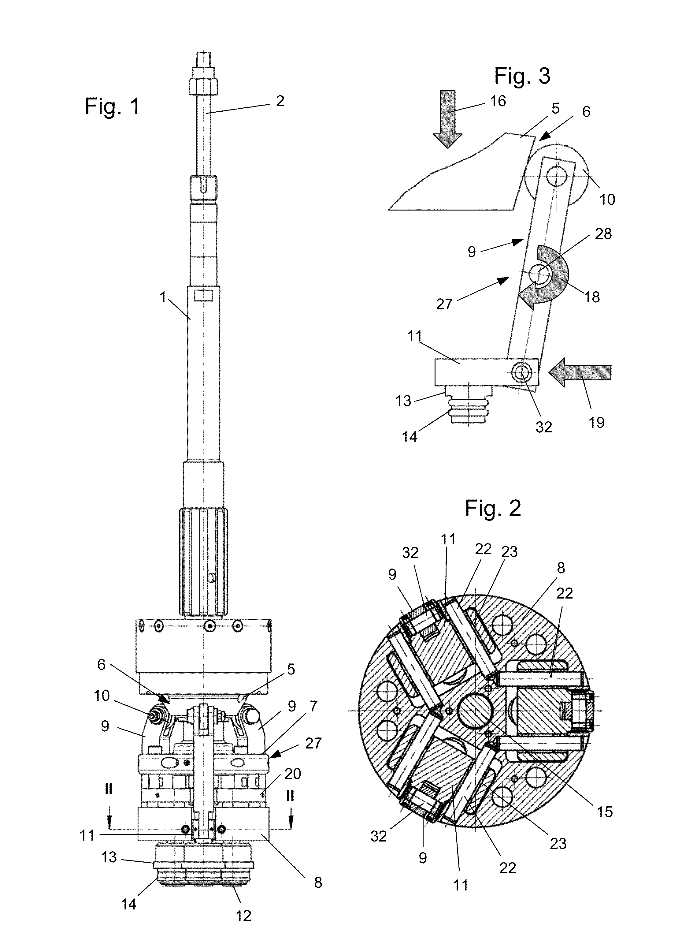
[0006]Since the shaping tool rotates, the workpiece, i.e. the inhaler cartridge which is to be produced, filled with a liquid active substance formulation, can be fixed in place, thereby preventing foaming of the active substance formulation. The shaping tool is positioned relative to the workpiece, while the bending roller is located in the position defining the maximum working aperture for the tool. By an adjusting movement using the lever, the bending roller is moved into the position defining the minimum working aperture for the tool. The profiled bending roller is matched to the contour that is to be produced and as a result of the radial adjustment an encircling radius, for example, is produced in rotationally symmetrical manner on an upper edge of the obviously cylindrical workpiece, whereby after an initial adjustment or determination of the diameter of the minimum working aperture for the tool a reliable product which is accurate in its shape and dimensions is obtained. The resetting of the bending roller from the minimum working aperture for the tool to the maximum working aperture for the tool is carried out by means of a radially acting compression spring.
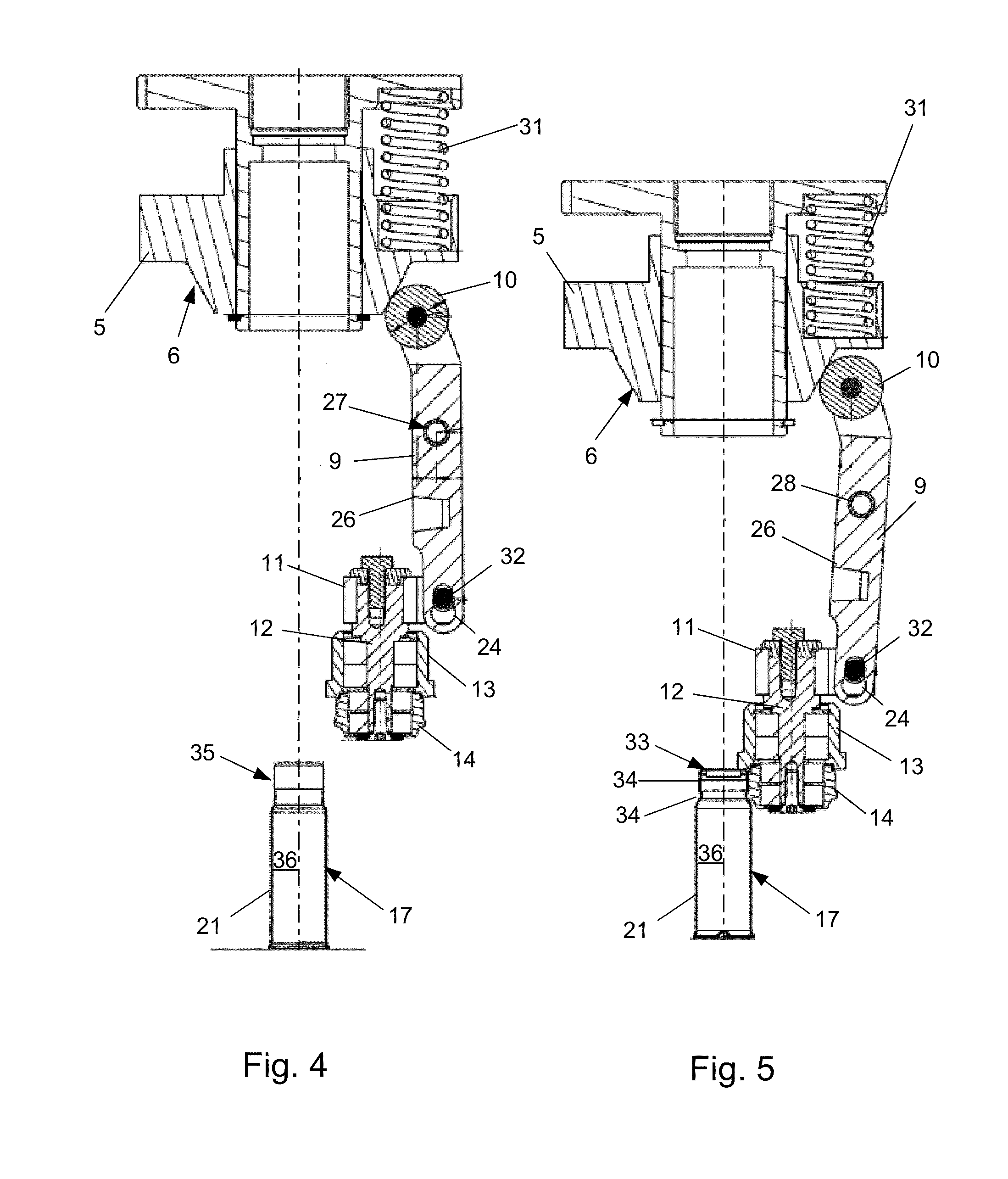
[0011]Preferably the pressing member is resiliently mounted in the axial direction. When the bending roller is in its radial end position, in which it describes the minimum working aperture for the tool and the final dimensions of the workpiece have been achieved, the pressing member moves counter to the spring force acting upon it, in order to prevent further advancing of the bending roller with resultant destruction of the workpiece. However with the spring-loaded overload prevention device it is also possible to generate the pressure needed to ensure the deformation and any tolerances in the workpiece can be equalised. The resilience associated with the pressing member may be effective both with an undersized workpiece and with an oversized one and will always clamp the bending roller against the workpiece. To provide the spring force, a central compression spring may be arranged or a plurality of compression springs uniformly distributed over the circumference of the pressing member may be provided.
[0014]Expediently, three radially adjustable slides each having one lever are arranged in a star shape with one another. The workpiece can be shaped relatively uniformly with the equidistantly distributed bending and shaping rollers and a high surface quality can be achieved at a high shaping speed while adhering to relatively narrow tolerances of form and dimensions.

Problems solved by technology

In the event of incorrect axial positioning, the pressing member would act upon the lever too early or too late, resulting in a defective and in particular non-gastight end contour.

Method used


Image

  • Shaping tool having a rotatable base member
  • Shaping tool having a rotatable base member
  • Shaping tool having a rotatable base member

Examples


Embodiment Construction

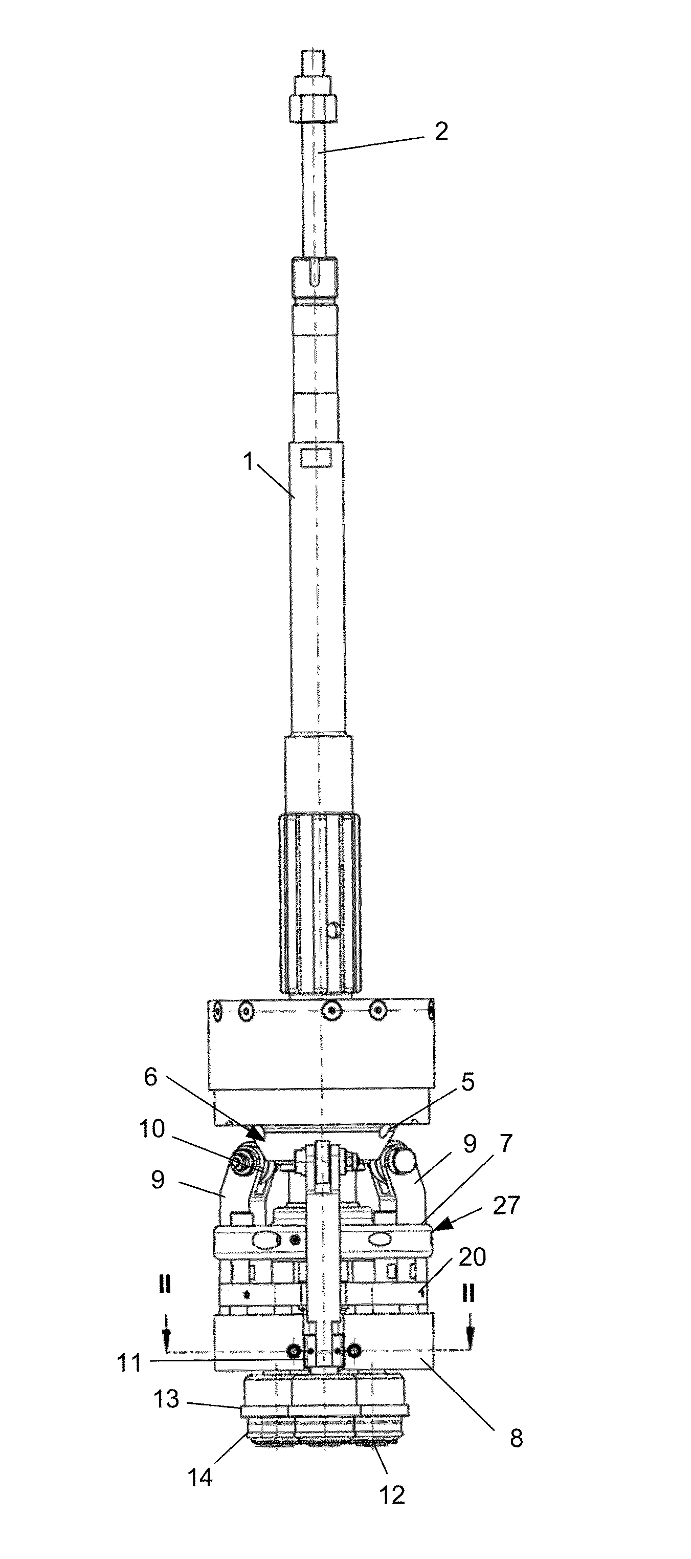
[0026]The shaping tool comprises a rod 2 mounted in a hollow shaft 1 and connected to a rotary drive (not shown). An axial up and down movement of the shaping tool is controlled by means of a radially mounted cam roller on the tool side, which cooperates with a cam control. In a housing (not shown) are various mounting, coupling and spring elements.

[0027]Underneath the housing is secured a pressing member 5 with a conical region 6 and underneath the pressing member 5 are a carrier member 7 and a guide portion 8, while pivotably mounted in the carrier member 7 are three levers 9 which comprise, at one end, rollers 10 cooperating with the pressing member 5, while the opposite ends from the rollers 10 act upon slides 11 mounted in the guide portion 8. Each of the slides 11 has a bending roller 13 and a shaping roller 14 on a spindle 12. For guiding the slide lithe guide portion 8 is fitted with guide bolts 22 aligned parallel and at a spacing from one another and the slides 11 are prov...


PUM

PropertyMeasurementUnit
axial movementaaaaaaaaaa
shapeaaaaaaaaaa
flexibleaaaaaaaaaa

Abstract

A shaping tool as depicted in exemplary FIG. 3 comprising a rotatable base member having at least one profiled bending roller (13) which is mounted on a circular track and is rotatable about a rotation axis. The bending roller (13) arranged on a radially movable slide (11) is movable from a position defining a maximum working aperture for the tool, by means of a spring-loaded lever (9) which has an axial configuration, into a position defining a minimum working aperture for the tool.

Description

[0001]The invention relates to a shaping tool which comprises a rotatable base member having at least one profiled bending roller which is mounted on a circular track and is rotatable about a rotation axis.BACKGROUND OF THE INVENTION[0002]For administering inhalable pharmaceutical formulations of active substances, the patient uses hand-held, manually operated inhalers in which the pharmaceutical active substance formulation is contained in an inhaler cartridge. The inhaler cartridge consists of an external aluminium cartridge and a plastic container inserted therein, the plastic container being produced by co-extrusion and comprising a rigid outer container and a flexible inner pouch disposed inside it. In order to create a pressure equalisation opening between the inner pouch and the outer container, an opening is formed in the relatively rigid outer container by the so-called cut-crack-open process, for example. The plastic container is filled with the pharmaceutical active subst...

Claims


Application Information

Patent Timeline
Patent Type & Authority Patents(United States)
IPC IPC(8): B21D1/02
CPCB21D17/04B21D39/04B21D51/24B21D51/2615B21D51/263B21D51/2638B21D51/32A61M15/0065A61M15/009B05B11/3091B05B11/1091
Inventor HAHN, CHRISTOPHMATHE, GERALDHUEBNER, MICHAEL
Owner BOEHRINGER INGELHEIM INT GMBH
Why Eureka
Try Eureka