Structural panels for use in aircraft fuselages and other structures

a technology for aircraft fuselages and other structures, applied in the field of structural panels, can solve the problems of labor-intensive assembly procedures, relatively expensive tooling, and conventional methods for manufacturing airframes with composite materials

Active Publication Date: 2013-07-30
THE BOEING CO
View PDF145 Cites 3 Cited by
  • Summary
  • Abstract
  • Description
  • Claims
  • Application Information

AI Technical Summary

Benefits of technology

[0007]The present invention is directed generally toward structural panels for use in manufacturing aircraft and other structures. A structural panel configured in accordance with one aspect of the invention includes a skin and at least first and second stiffeners. The first stiffener can have a first flange portion mated to the skin and a first raised portion projecting away from the skin. The second stiffener can be spaced apart from the first stiffener and can have a second flange portion mated to the skin and a second raised portion projecting away from the skin. The structural panel can further include a frame section having a base portion mated to the first flange portion of the first stiffener and the second flange portion of the second stiffener without being mated to the skin between the first raised portion of the first stiffener and the second raised portion of the second stiffener. In another aspect of the invention, at least one of the first flange portion of the first stiffener and the second flange portion of the second stiffener can extend toward the other to form an at least approximately continuous support surface extending between the first raised portion of the first stiffener and the second raised portion of the second stiffener.
[0008]An aircraft fuselage configured in accordance with another aspect of the invention includes a passenger cabin and a plurality of structural panels operably coupled together to form a portion of the passenger cabin. Individual s

Problems solved by technology

Conventional methods for manufacturing airframes with composite materials, however,

Method used


Image

  • Structural panels for use in aircraft fuselages and other structures
  • Structural panels for use in aircraft fuselages and other structures
  • Structural panels for use in aircraft fuselages and other structures

Examples


Embodiment Construction

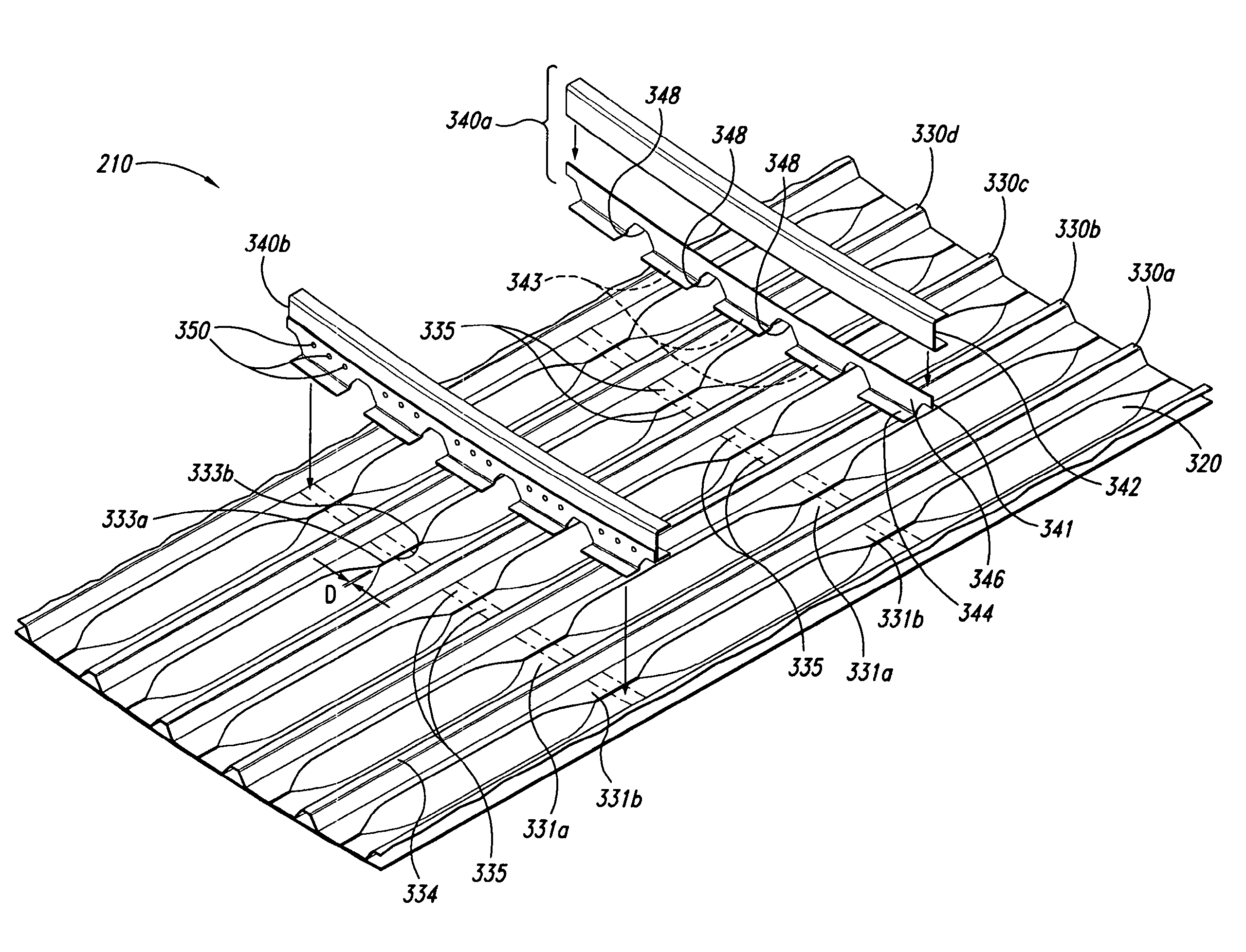
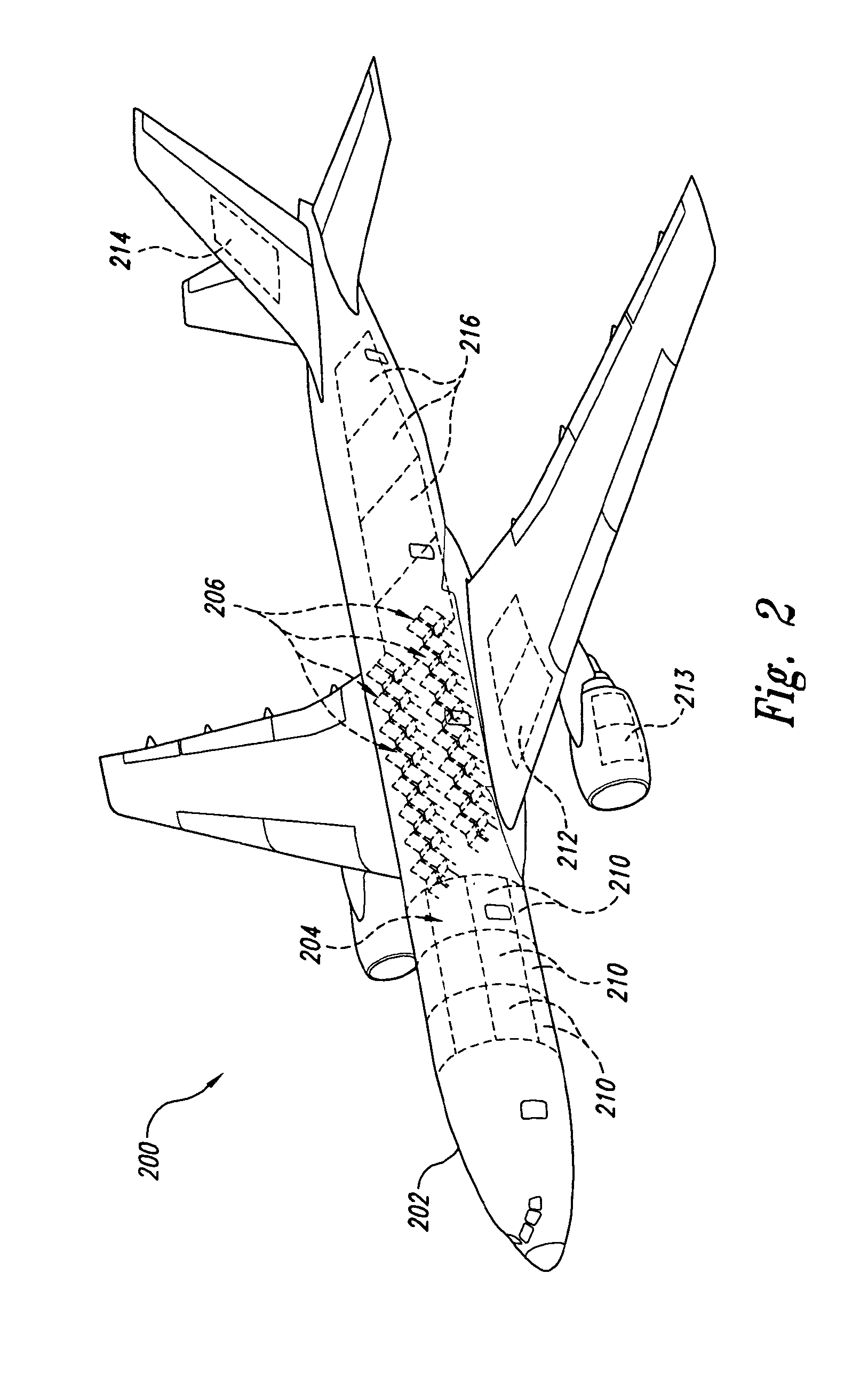
[0016]The following disclosure describes structural panels for use in manufacturing aircraft and other structures. Certain details are set forth in the following description and in FIGS. 2-6B to provide a thorough understanding of various embodiments of the invention. Other details describing well-known structures and systems often associated with aircraft structures and composite materials are not set forth in the following disclosure to avoid unnecessarily obscuring the description of the various embodiments of the invention.

[0017]Many of the details, dimensions, angles, and other features shown in the Figures are merely illustrative of particular embodiments of the invention. Accordingly, other embodiments can have other details, dimensions, angles, and features without departing from the spirit or scope of the present invention. In addition, further embodiments can be practiced without several of the details described below.

[0018]In the Figures, identical reference numbers ident...


PUM

PropertyMeasurementUnit
Distanceaaaaaaaaaa
Distanceaaaaaaaaaa

Abstract

Structural panels for use in manufacturing aircraft fuselages and other structures are disclosed herein. In one embodiment, a structural panel configured in accordance with the invention includes a skin and at least first and second stiffeners. The first stiffener can have a first flange portion mated to the skin and a first raised portion projecting away from the skin. The second stiffener can have a second flange portion mated to the skin and a second raised portion projecting away from the skin. At least one of the first flange portion of the first stiffener and the second flange portion of the second stiffener can extend toward the other of the first flange portion and the second flange portion to form an at least approximately continuous support surface to which a frame can be attached.

Description

CROSS-REFERENCE TO RELATED APPLICATION:[0001]The present application claims priority to U.S. Provisional Patent Application No. 60 / 559,991, entitled “STRUCTURAL PANELS FOR USE IN AIRCRAFT FUSELAGES AND OTHER STRUCTURES,” filed Apr. 6, 2004, and incorporated herein in its entirety by reference. This application is a divisional of application Ser. No. 11 / 522,184, filed Sep. 14, 2006, status allowed.TECHNICAL FIELD[0002]The following disclosure relates generally to structural panels and, more particularly, to structural panels for use in aircraft fuselages and other structures.BACKGROUND[0003]Aircraft manufacturers continually strive for ways to increase aircraft performance and reduce manufacturing costs. One well-known method for increasing aircraft performance is to reduce airframe weight through the use of state-of-the-art materials, such as composites, having relatively high strength-to-weight ratios. Conventional methods for manufacturing airframes with composite materials, howev...

Claims


Application Information

Patent Timeline
IPC IPC(8): B64C1/00B29D99/00B61D17/04B63B3/28B63B3/36B64C1/06B64C1/12B64C3/18B64C3/26
CPCB61D17/041B63B3/28B63B3/36B64C1/12B64C3/182B64C3/26B64C2001/0072B64C2001/0081Y02T50/40Y10T29/49616Y10T29/49622Y10T29/53978Y10T156/1089Y10T428/24033Y10T428/24174Y10T428/24182Y10T428/24198
Inventor JOHNSON, KENT E.ULVIN, MARK A.
Owner THE BOEING CO
Why Eureka
Try Eureka