Bump stop and associated MacPherson strut

a technology of a strut and a clamping device, which is applied in the direction of shock absorbers, bearing unit rigid supports, transportation and packaging, etc., can solve the problems of light relative axial movement, and achieve the effect of simple installation and good operating safety

Inactive Publication Date: 2013-07-30
AB SKF
View PDF13 Cites 22 Cited by
  • Summary
  • Abstract
  • Description
  • Claims
  • Application Information

AI Technical Summary

Benefits of technology

[0010]More particularly, the object of the present invention is to provide a bump sto...

Problems solved by technology

Specifically, there is usually an axial clearance between the bottom end of the subassembly and the...

Method used


Image

  • Bump stop and associated MacPherson strut
  • Bump stop and associated MacPherson strut
  • Bump stop and associated MacPherson strut

Examples


Embodiment Construction

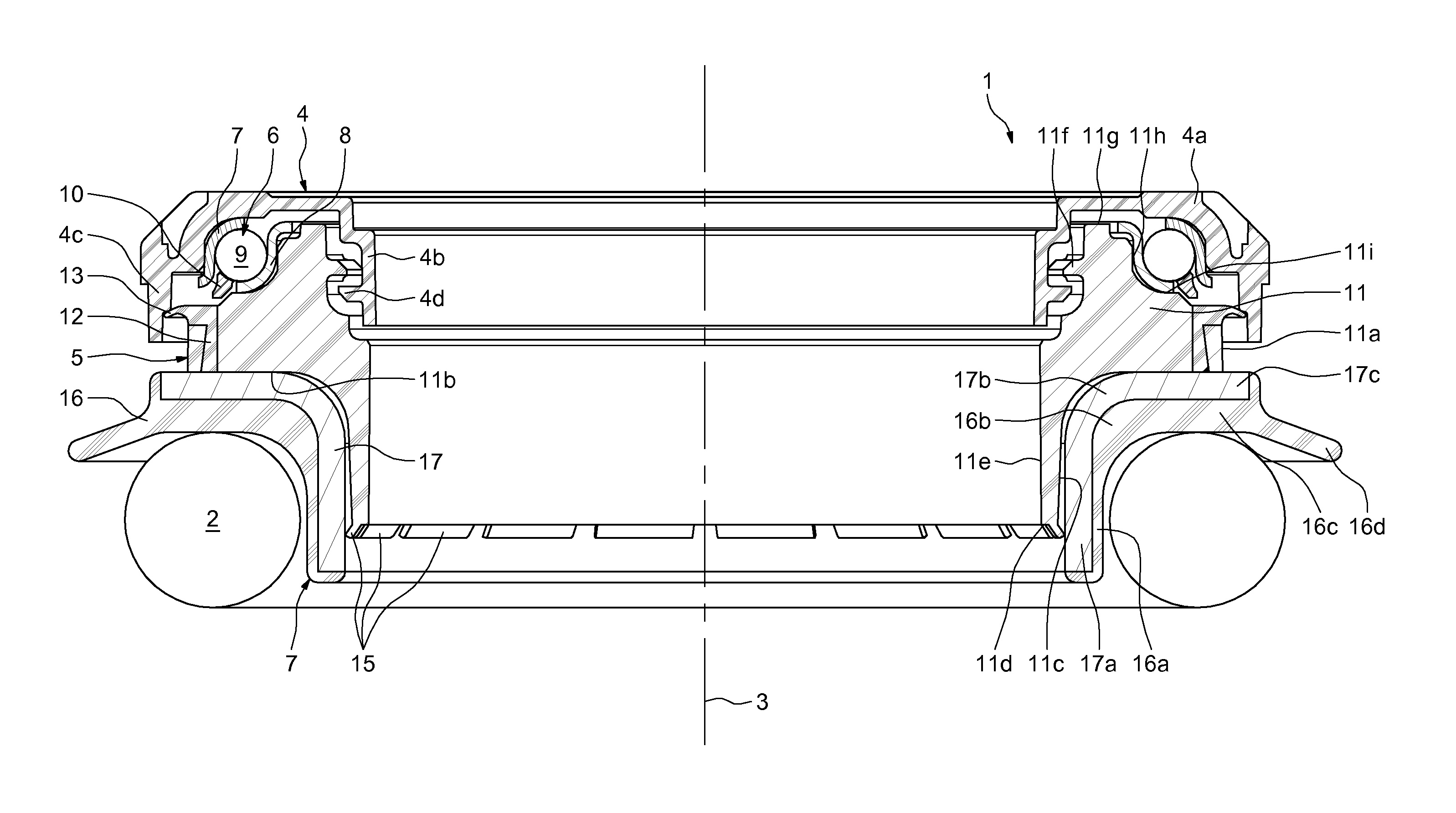
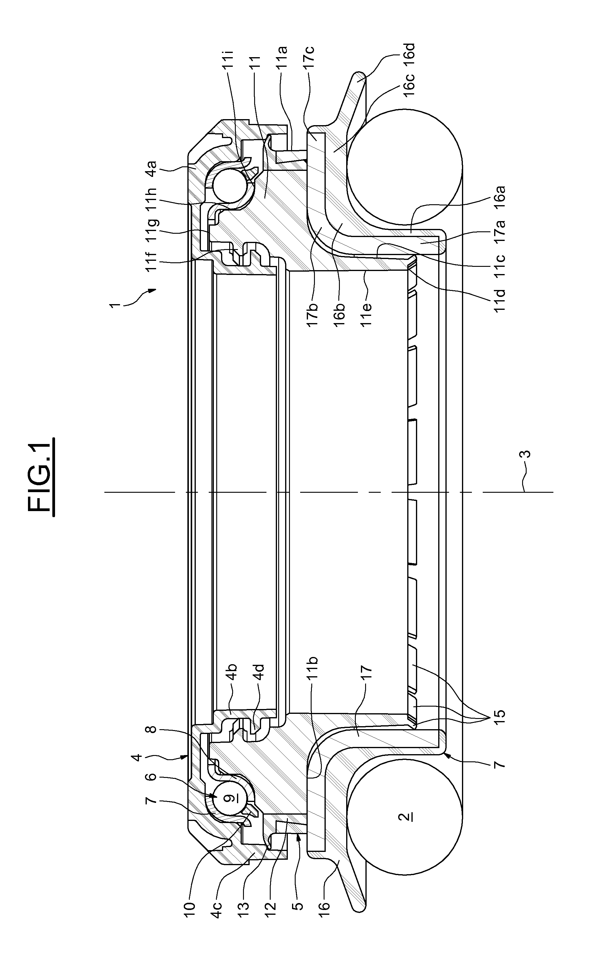
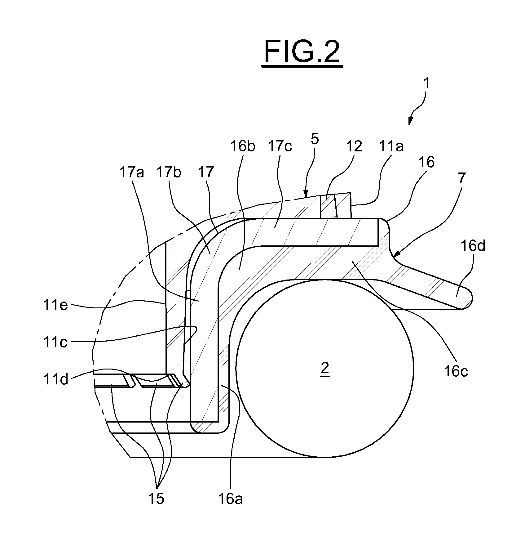
[0024]FIGS. 1 and 2 show a bump stop device, indicated by the general reference number 1, and designed to be installed between a top retainer seat (not shown) capable of resting, directly or indirectly, in an element of a chassis of the motor vehicle, and a helical spring 2. The bump stop 1 is placed around a shock absorber rod (not shown) extending on a substantially vertical axis 3, the spring 2 being installed around the said rod.

[0025]The bump stop 1 mainly comprises a top support cover 4, a bottom support cover 5, a bearing 6 placed axially between the said covers, and a bottom retainer 7 for the spring 2.

[0026]The top cover 4 may consist of a one-piece part made of a plastic material, for example of polyamide PA 6.6 which may or may not be reinforced with glass fibres. The top cover 4 comprises a top radial portion 4a designed to be in contact with the top retainer seat, an annular internal axial skirt 4b that is thin and of small diameter, and an annular external axial skirt ...


PUM


Abstract

The bump stop device, particularly for a motor vehicle, comprises a bearing 6 forming an axial stop, a bottom support cover 5 of the bearing and a bottom retainer 7 for a spring comprising at least one stiffening strut. The support cover 5 and/or the retainer 7 comprises at least one axial securing means 15 of the bottom retainer and of the bottom support cover, the said means being situated axially set back from a bottom end of the retainer.

Description

CROSS REFERENCE TO RELATED APPLICATIONS[0001]This application is the U.S. National Phase Application of PCT / EP2009 / 062308, filed Sep. 23, 2009, which claims priority to French Patent Application No. 0856495, filed Sep. 26, 2008, the contents of such applications being incorporated by reference herein.BACKGROUND OF THE INVENTION[0002]The present invention relates to the field of bump stop devices used in particular on motor vehicles in the MacPherson struts of the steering wheels.[0003]Conventionally, a bump stop is provided with a top race and a bottom race between which rolling elements and bottom and top retaining or support elements are placed such as covers, forming housings for the bottom and top races of the bearing respectively.[0004]A bump stop is placed in the top portion of the MacPherson strut between a suspension spring and a top element secured to the bodywork of the vehicle. The suspension spring is placed around a shock absorber piston rod the end of which may be secu...

Claims


Application Information

Patent Timeline
IPC IPC(8): F16C19/30
CPCB60G15/068F16C19/10F16C33/761F16C35/04B60G2204/128B60G2204/418B60G2300/0262F16C2326/05
Inventor VIAULT, SAMUELPOULLE, THIERRY
Owner AB SKF
Why Eureka
Try Eureka