
Rebounding apparatus

a technology of rebounding and equipment, which is applied in the direction of weapons, targets, racket sports, etc., can solve the problems of not being able to withstand heavy or prolonged use, and many of the rebounders currently found in the marketplace, and achieves the effect of robust design andrugged design

Inactive Publication Date: 2013-07-30
BULLOCH RONALD C
View PDF40 Cites 2 Cited by
  • Summary
  • Abstract
  • Description
  • Claims
  • Application Information

AI Technical Summary

Benefits of technology

The present invention is a rebounder that is very durable and can be made at a low cost.

Problems solved by technology

Many of the rebounders currently found in the marketplace, however, are not built to withstand heavy or prolonged usage.

Method used


Image

  • Rebounding apparatus
  • Rebounding apparatus
  • Rebounding apparatus

Examples


Embodiment Construction

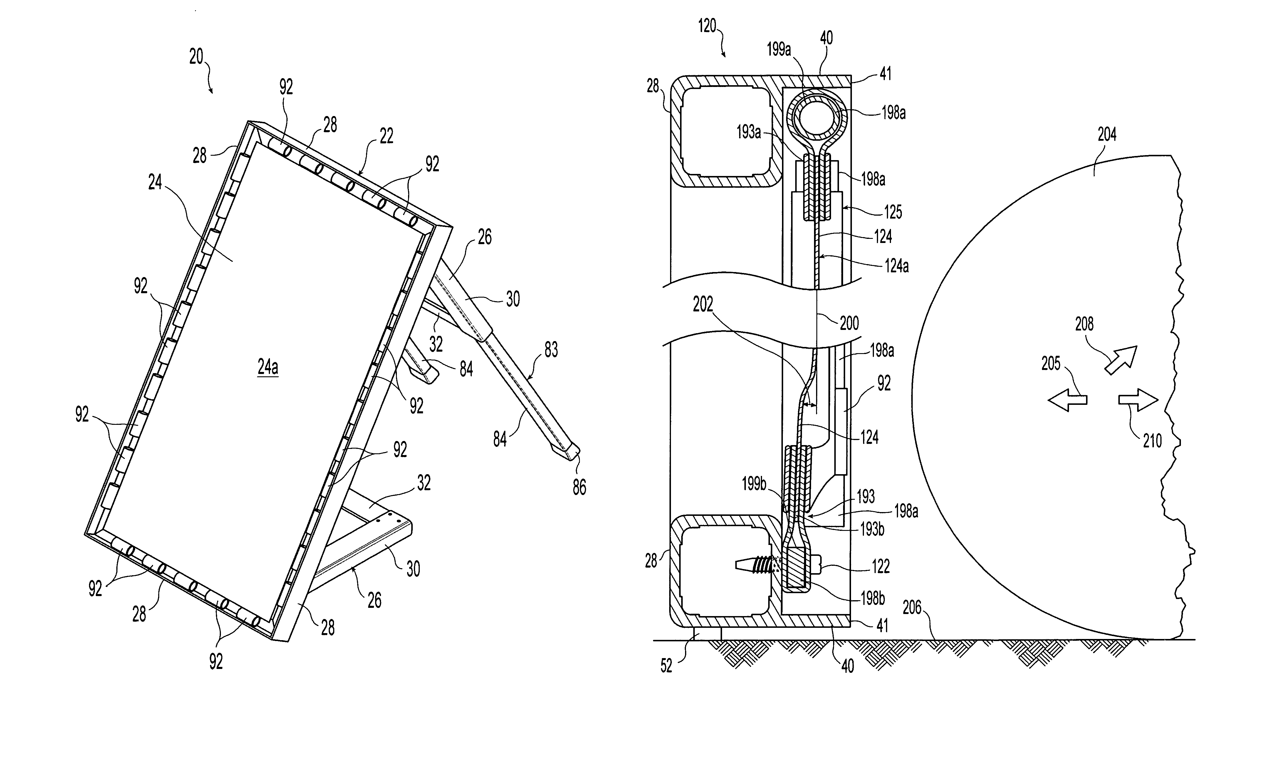
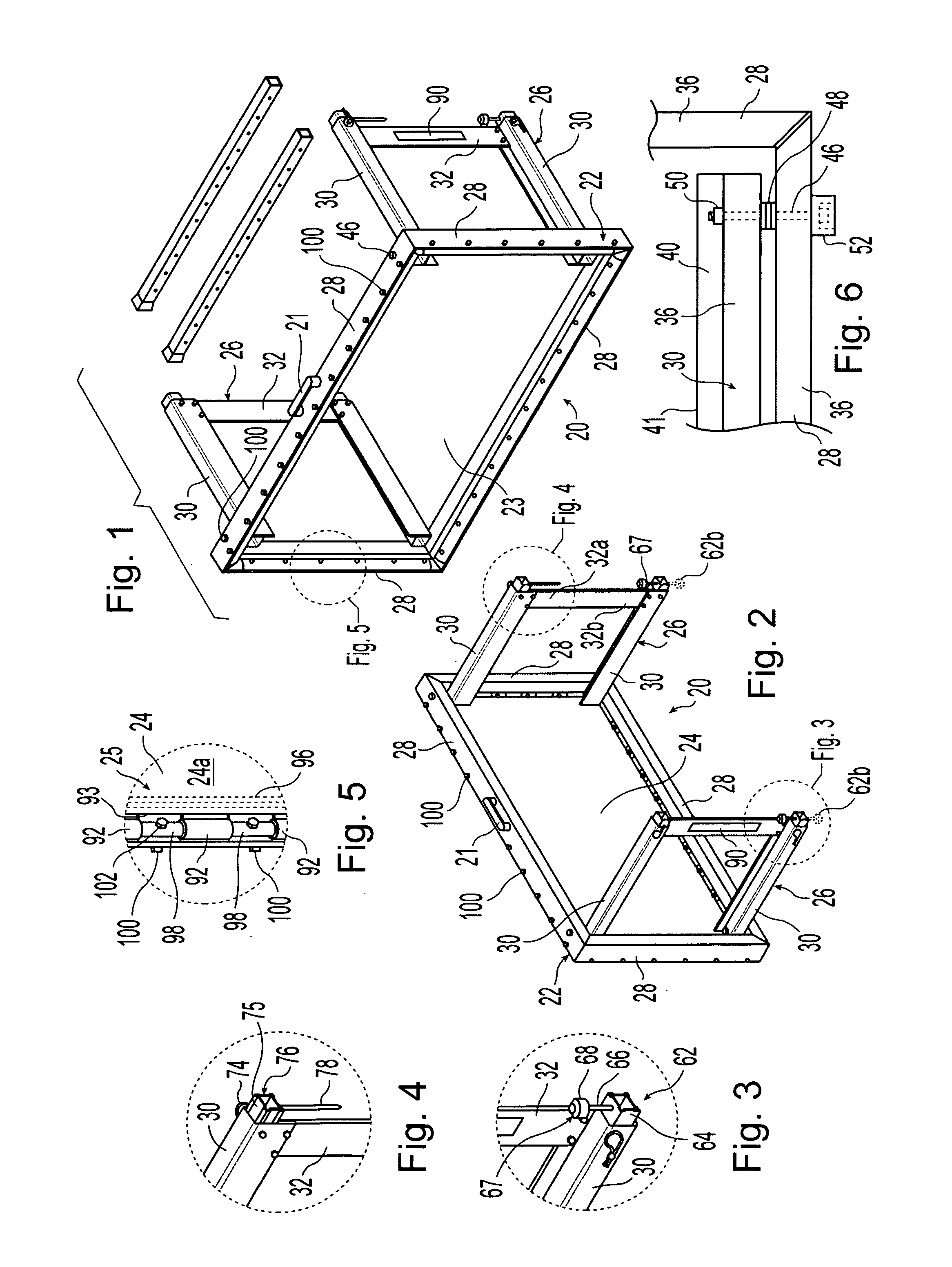
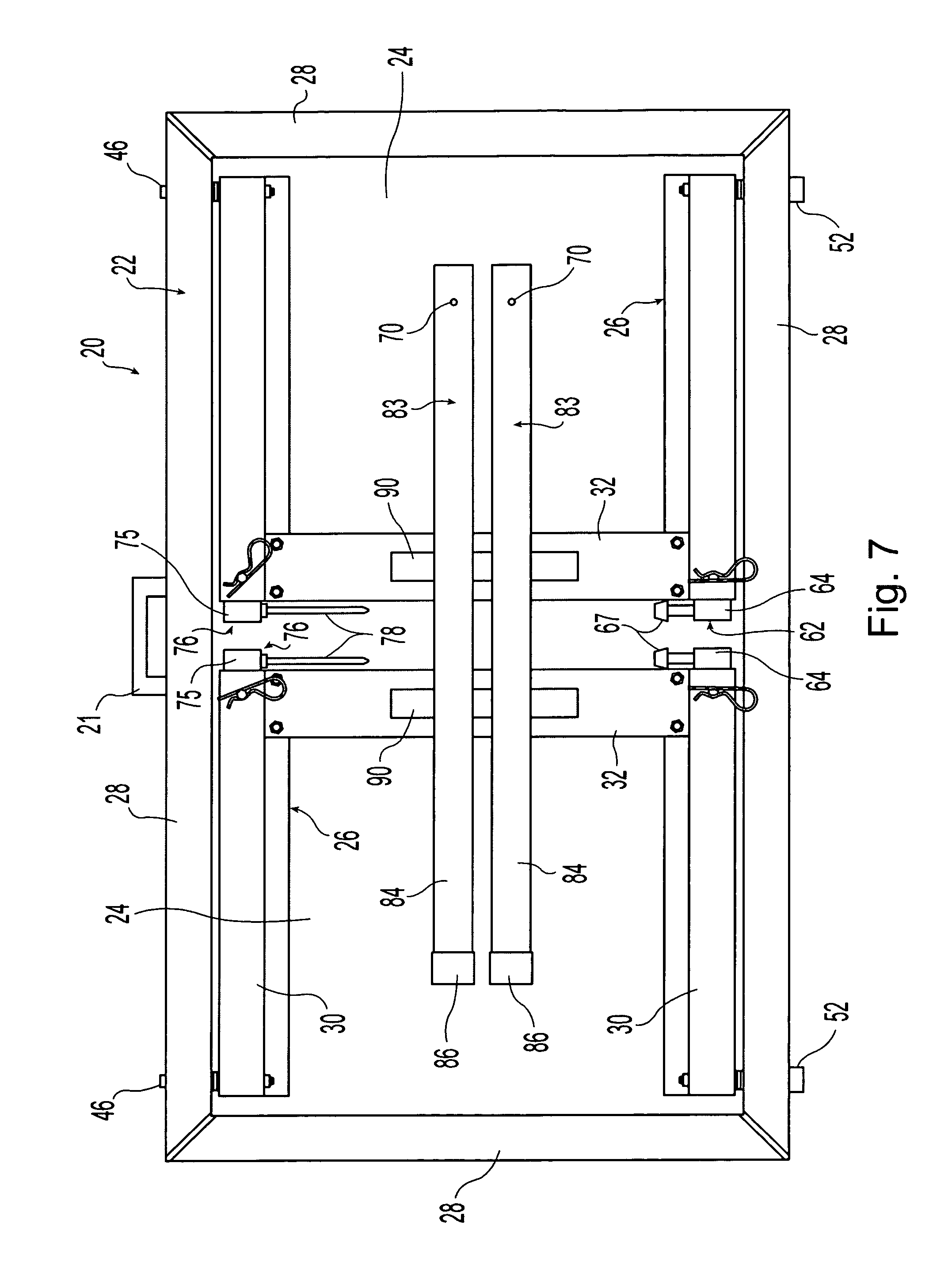
[0029]A rebounder 20 in accordance with the present invention is shown in FIGS. 1 and 2. Rebounder 20 includes a structural frame 22 with a central opening 23 defining an axis 20a, a bounceback assembly 25 having a rebounding member formed by a flexible sheet of material 24, and leg assemblies 26. It is noted that rebounding member 24 and tensioning members 92 have been omitted from FIG. 1 for purposes of graphical clarity.

[0030]In the illustrated embodiment, frame 22 is formed by welding four frame members 28 together to form a four-sided rectilinear frame 22. The illustrated frame 22 has a length of approximately 42 inches and a width of approximately 24 inches and is well suited for use in rebounding soccer balls. Rebounders 20 can also be used when training for other sports. For example, rebounder 20 can also be used to rebound projectiles other than soccer balls such as baseballs or lacrosse balls. To better adapt rebounder 20 to other sports, alternative embodiments of rebound...


PUM


Abstract

A rebounding apparatus for returning soccer balls, baseballs and similar projectiles. The apparatus includes a rigid frame with a rebounding surface suspended within the frame. Pivotal support assemblies are used to support the apparatus in both horizontal and vertical orientations. The apparatus can be folded into a compact configuration for transport or storage.

Description

CROSS REFERENCE TO RELATED APPLICATIONS[0001]This application claims priority under 35 U.S.C. 119(e) of U.S. provisional patent application Ser. No. 61 / 275,094 filed on Aug. 25, 2009 entitled REBOUNDING APPARATUS the disclosure of which is hereby incorporated herein by reference.BACKGROUND OF THE INVENTION[0002]1. Field of the Invention[0003]The present invention relates to athletic training equipment and, more specifically, to a device that can be used for rebounding activities such as rebounding a soccer ball.[0004]2. Description of the Related Art[0005]The use of rebounding devices to return a soccer ball, baseball or other object to a user after that person has kicked, thrown or otherwise projected the ball at the rebounder is known in the art. Many of the rebounders currently found in the marketplace, however, are not built to withstand heavy or prolonged usage.SUMMARY OF THE INVENTION[0006]The present invention provides a rebounder having a rugged and robust design that can be...

Claims


Application Information

Patent Timeline
Patent Type & Authority Patents(United States)
IPC IPC(8): A63B69/34
CPCA63B69/0097A63B69/0002A63B69/002A63B2209/10A63B2210/50A63B2243/005A63B2102/14
Inventor BULLOCH, RONALD C.
Owner BULLOCH RONALD C
Learn More