
Rotary derrick cap
A pole-holding cap and pole-holding technology, which is applied in towers, building types, buildings, etc., can solve the problems of easy occurrence of safety accidents, unfavorable to conventional construction, and large limitations of holding poles, so as to reduce engineering costs and improve construction efficiency. and safety and weight reduction effects
- Summary
- Abstract
- Description
- Claims
- Application Information
AI Technical Summary
Problems solved by technology
Method used
Image

Examples
Embodiment Construction
[0026] Below in conjunction with embodiment the present invention is described in further detail:
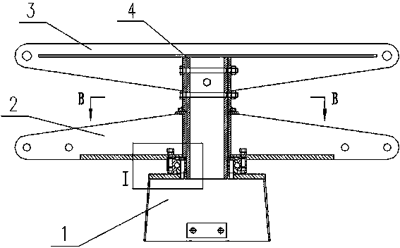
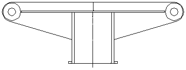
[0027] The structure of the present invention is as figure 1 As shown, it includes a sleeve cap 1 for connecting the pole body, the upper end surface of the sleeve cap 1 is fixedly connected with a cylindrical column 4, the column 4 is vertically arranged with the sleeve cap 1, and the outer peripheral wall of the column 4 is sequentially arranged from bottom to top A lifting assembly 2 and a wire frame 3 matched with the outer circumference of the column 4 are arranged.
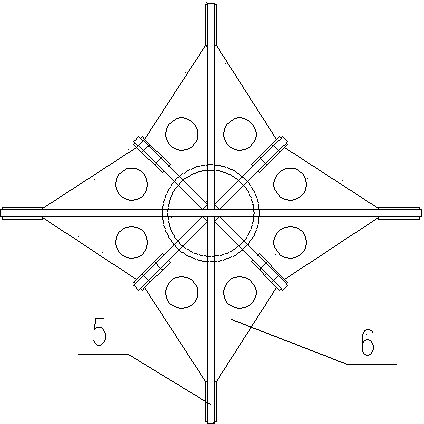
[0028] The structure of lifting assembly 2 is as Figure 4 , Figure 5 As shown, it includes a square support frame, which is a frame structure, and the square support frame is set on the column 4 through the central cylinder and can rotate around the column 4 . A flat plate 12 is welded below the square support frame, and the flat plate 12 is welded together with the bottom surface of the cylinder at the c...
PUM
 Abstract
Description
Claims
Application Information