Microfluidics polymerase chain reaction and high resolution melt detection

a polymerase chain reaction and microfluidics technology, applied in the field of microfluidics, high-resolution melt analysis and microfluidics, to achieve the effect of arugged design

Active Publication Date: 2017-08-01
SYRACUSE UNIVERSITY
View PDF14 Cites 0 Cited by
  • Summary
  • Abstract
  • Description
  • Claims
  • Application Information

AI Technical Summary

Benefits of technology

[0008]It is therefore a principal object and advantage of the present invention to provide a microfluidics-based PCR and HRM method and system that eliminates / alleviates one or more of the problems / issues with conventional related technologies.
[0009]It is a further object and advantage of the present invention to provide a microfluidics-based PCR and HRM method and system that addresses the need of a fieldable PCR that can be detected without the need of a fluorescent dye, expensive / fragile light source, or an optics system for detection.
[0010]Another object and advantage of the present invention is to provide a microfluidics-based PCR and HRM method and system that combines the processes necessary for amplification of DNA (PCR) and HRM and their subsequent detection into a single, fieldable device. The device can be small, lightweight, and have a rugged design for which no use of fluorescence and optics is required.
[0011]Another object and advantage of the present invention is to provide a microfluidics-based PCR and HRM method and system that combines the use of microfluidics for PCR with direct detection of DNA products (including detection of DNA based on its charge properties). The improvements gained by an embodiment of the present invention include, but are not limited to: 1. The combination of these two processes on a single “chip”; 2. Direct detection of DNA hybridization dynamics on a “chip”.
[0012]In accordance with the following objects and advantages, an embodiment of the present invention provides a microfluidics-based PCR and HRM method and system that provides a “closed track” where PCR could take place, e.g., one oval-like track per assay. When cycling finished, a portion of the total amplicon is sent to a potentiometric monitoring chamber that is preloaded with a polyaniline layer, for example, and allowed to adsorb (or pre-loaded w / reference DNA, and blocked w / thiol groups), then another portion of the amplicon is sent to the chamber and allowed to anneal, change in voltage measured, denature w / temp increase and measure change in voltage→interpreted as melt curve→ID.

Problems solved by technology

The concept of doing PCR “on a chip” or using microfluidics is not fieldable by conventional technology at this time because no rugged detection system exists, most being based on fluorescence and optics.

Method used


Image

  • Microfluidics polymerase chain reaction and high resolution melt detection
  • Microfluidics polymerase chain reaction and high resolution melt detection

Examples


example

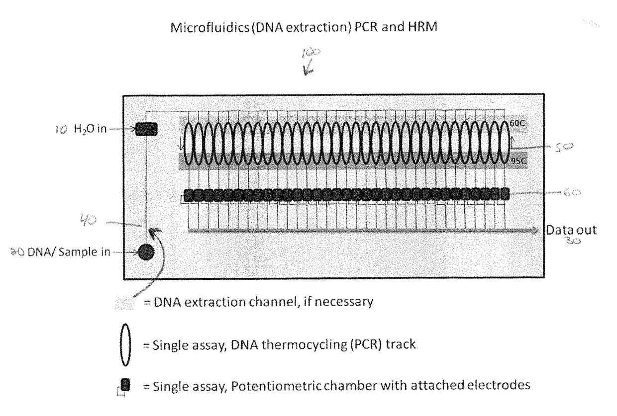
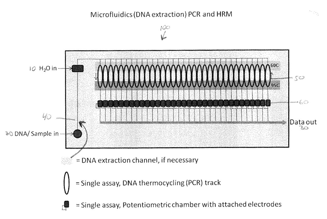
[0019]This Example describes a use of the micro-scaled microfluidics-based PCR and HRM system 100. Reaction components are preloaded into specific assay chambers. At the time of use, user-supplied DNA is injected via an onboard pump (not shown) into all chambers and the subsequent PCR reactions carried out by pumping the reactions back and forth across a temperature gradient from approximately 60 C to 95 C for a given number of cycles. After cycling and a final exposure to 95 C, the reactions are pumped into an HRM chamber preloaded with an electrode polymer, a single-stranded reference DNA (being the same length as the PCR product), and “empty” spaces in the electrode being blocked with thiol groups. These chambers are rapidly cooled from 95 C to 55 C and the concomitant ionic changes detected by the electrode and transmitted to onboard data collection.

[0020]In an alternative format, after the final exposure to about 95 C following cycling, the DNA is cooled to about 55 C and then ...


PUM

PropertyMeasurementUnit
temperatureaaaaaaaaaa

Abstract

The present invention relates to a method and system for Polymerase Chain Reaction (“PCR”), High Resolution Melt (“HRM”) analysis and microfluidics, and, more specifically, to a method and system for implementing the processes of PCR and HRM on a microscale in a microfluidics chamber for certain purposes including for purposes of DNA detection and / or extraction.

Description

RELATED APPLICATION DATA[0001]The present application claims the benefit of U.S. provisional patent application Ser. No. 61 / 799,165, filed Mar. 15, 2013, and is hereby incorporated by reference in its entirety.BACKGROUND OF THE INVENTION[0002]1. Field of the Invention[0003]The present invention relates to a method and system for Polymerase Chain Reaction (“PCR”), High Resolution Melt (“HRM”) analysis and microfluidics, and, more specifically, to a method and system for implementing the processes of PCR and HRM on a microscale in a microfluidics chamber for certain purposes including for purposes of DNA detection and / or extraction.[0004]2. Description of the Related Art[0005]Polymerase Chain Reaction (“PCR”) is a ubiquitous molecular biology tool used in thousands of different applications. In brief, this molecular biology tool is used to produce (“amplify”) a sufficient number (sometimes millions to billions) of copies of a particular DNA sequence so that the sequence can adequately...

Claims


Application Information

Patent Timeline
Patent Type & Authority Patents(United States)
IPC IPC(8): C12Q1/68B01L3/00B01L7/00
CPCB01L3/502715B01L7/525B01L2300/0645B01L2300/088B01L2300/0816B01L2300/0864B01L2400/0487
Inventor CADLE-DAVIDSON, MOLLY M.
Owner SYRACUSE UNIVERSITY
Why Eureka
Try Eureka