
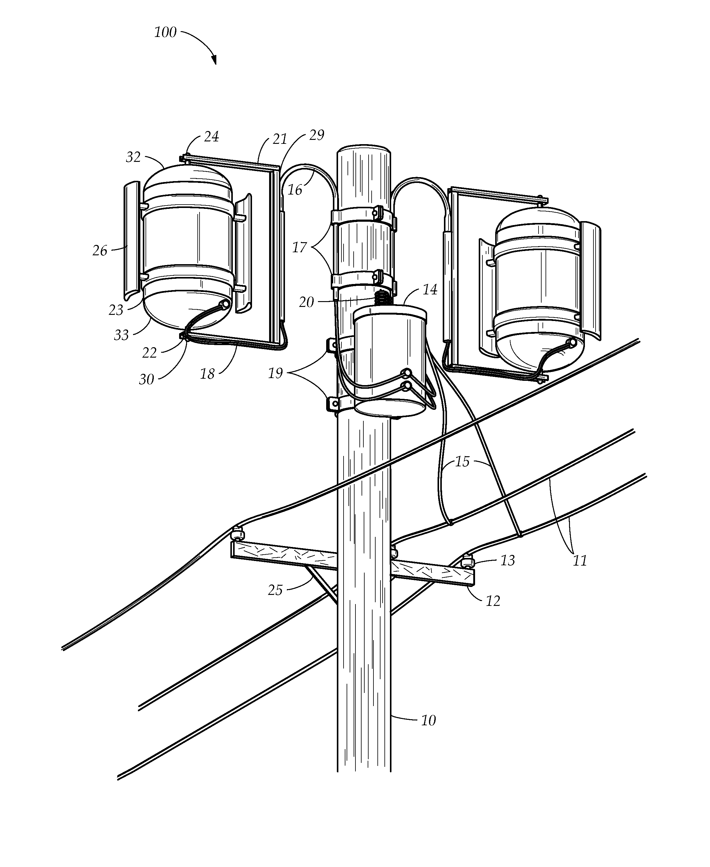
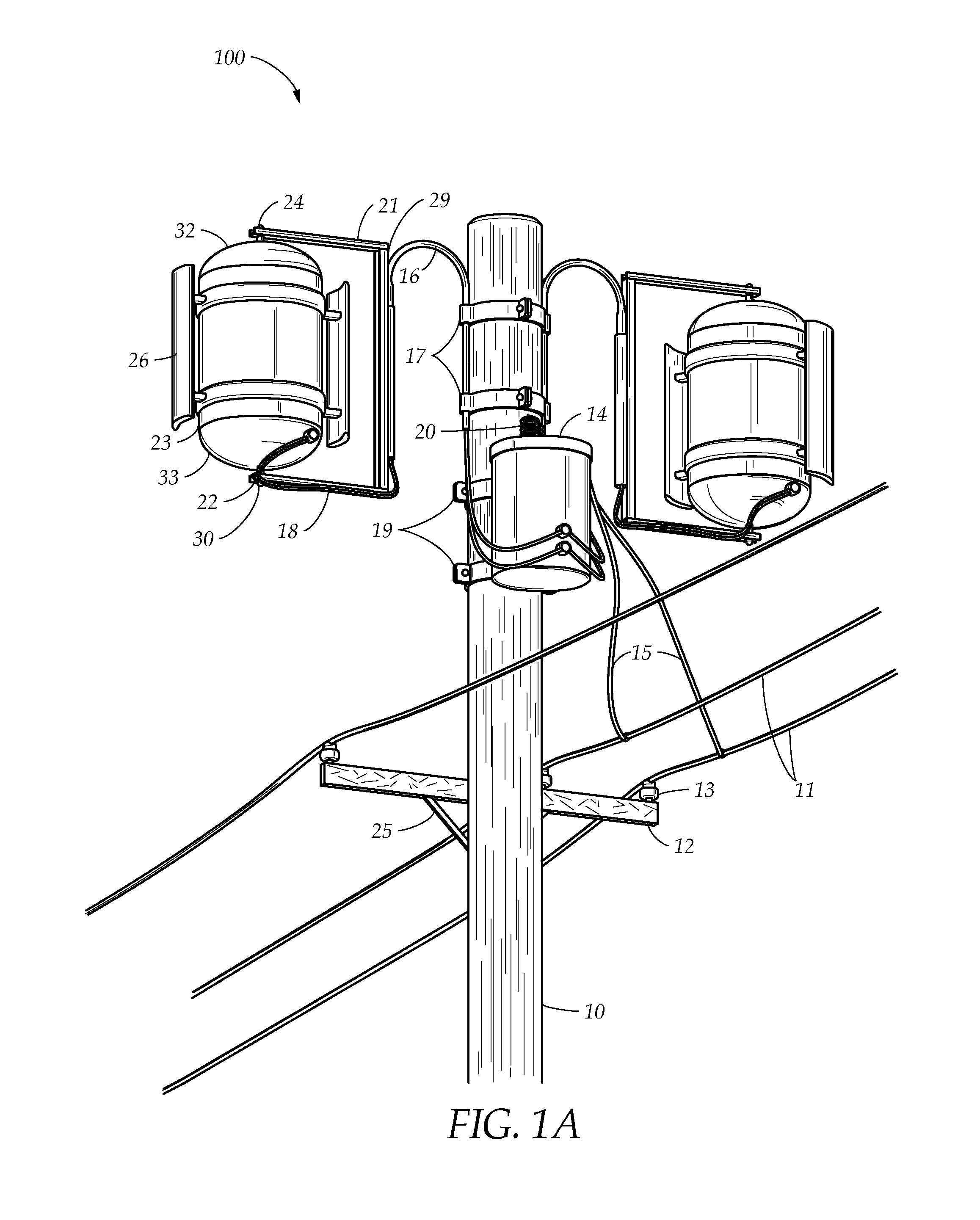
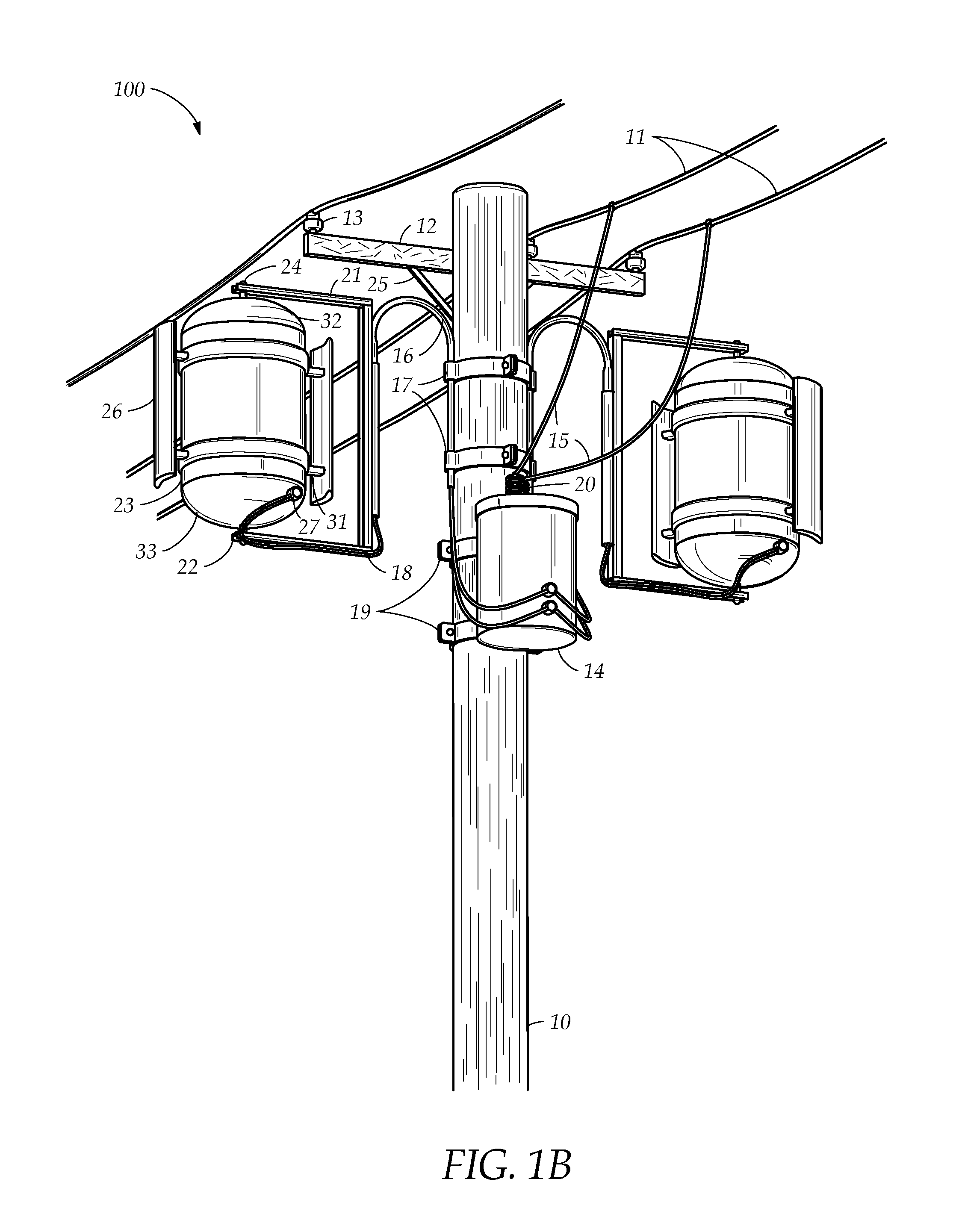
Utility pole mountable vertical axis wind turbine

a technology of wind turbines and poles, applied in the field of wind turbines, can solve the problems of significant economic investment, visual pollution and contentious land use issues, and significant amount of wind energy, which often encounters these poles, and cannot control the rising energy cos

Active Publication Date: 2013-07-30
JONES THOMAS
View PDF10 Cites 31 Cited by
  • Summary
  • Abstract
  • Description
  • Claims
  • Application Information

AI Technical Summary

Benefits of technology

The patent text describes a vertical axis wind turbine that can be attached to a utility pole. The turbine includes a housing that rotates on a vertical axis and with respect to the support arms, and a plurality of blades that extend in a vertical direction. A generator is stationed within the space defined by the housing and generates an electric current in response to the rotation of the housing due to wind. The invention provides a more efficient means of harnessing wind energy, making it easier to generate electricity from wind.

Problems solved by technology

Although wind farms with acres of large wind turbines have proved relatively successful, such wind farms are relatively rare and generally involve substantial economic investment, visual pollution and contentious land use issues.
A significant amount of wind energy, which often encounters these poles, remains underutilized.
Additionally, some electric utility companies, such as electric distribution cooperatives, do not generate electric power.
Thus, these companies are caught in the middle of a vibrant energy supply and demand market and, generally, do not have control over rising energy costs.
Similarly, these companies also often face arbitrary political mandates or unreasonable customer demands for prompt provision of renewable energy without having any control over how to provide such energy.

Method used


Image

  • Utility pole mountable vertical axis wind turbine
  • Utility pole mountable vertical axis wind turbine
  • Utility pole mountable vertical axis wind turbine

Examples


Embodiment Construction

[0019]The invention now will be described more fully hereinafter with reference to the accompanying drawings, in which various embodiments are shown. This invention may, however, be embodied in many different forms, and should not be construed as limited to the embodiments set forth herein. Rather, these embodiments are provided so that this disclosure will be thorough and complete, and will fully convey the scope of the invention to those skilled in the art. Like reference numerals refer to like elements throughout.

[0020]It will be understood that when an element is referred to as being “on” another element, it can be directly on the other element or intervening elements may be present therebetween. In contrast, when an element is referred to as being “directly on” another element, there are no intervening elements present. As used herein, the term “and / or” includes any and all combinations of one or more of the associated listed items.

[0021]It will be understood that, although the...


PUM


Abstract

A vertical axis wind turbine for attaching to a utility pole includes a plurality of support arms, a housing, a generator and a plurality of blades. The support arms attach to the utility pole. The housing is coupled between the arms. The housing includes an outer wall defining a space within the housing. The housing rotates on a vertical axis of rotation and with respect to the arms. The generator is stationed within the space. The generator generates an electric current in response to a rotation of the housing. The plurality of blades coupled to an external surface of the outer wall, one of the blades extends in a vertical direction.

Description

TECHNICAL FIELD[0001]The present invention relates to wind turbines, and more specifically, to a utility pole mountable vertical axis wind turbine.BACKGROUND[0002]Identification of new non-fossil fuel based energy sources, which are both commercially viable and environmentally benign, has become an important national security and technological need. With increasing domestic energy consumption, such technology will not only enhance national security, reduce visual pollution, fuel economic growth, create jobs and contribute to global environmental sustainability, but also reduce foreign energy dependence.[0003]Many countries and businesses often commit to make better use of renewable and nonpolluting energy sources. Wind energy is a popular source explored by many not just because wind energy is renewable and nonpolluting, but also because wind energy is free. Although wind farms with acres of large wind turbines have proved relatively successful, such wind farms are relatively rare a...

Claims


Application Information

Patent Timeline
IPC IPC(8): F03D9/00
CPCF03D9/00F05B2240/211F05B2240/913Y02E10/728Y02E10/74F03D3/02F03D80/70F03D80/40F03D13/20F03D9/34F03D9/25
Inventor JONES, THOMAS
Owner JONES THOMAS
Learn More