Projection system

a projection system and projection technology, applied in projectors, instruments, color television details, etc., can solve the problems of difficult image of the first tilting mirror matrix onto the second tilting mirror matrix, and difficult compact optical structure, etc., to achieve compact optical structure and good imaging quality.

Active Publication Date: 2013-08-06
CARL ZEISS JENA GMBH
View PDF82 Cites 5 Cited by
  • Summary
  • Abstract
  • Description
  • Claims
  • Application Information

AI Technical Summary

Benefits of technology

[0005]Starting from here, the object of the invention is to develop the projection system of the type named at the beginning such that a compact optical structure can be realized with simultaneously good imaging quality.
[0006]The object is achieved in the case of the projection system of the type named at the beginning in that the imaging optics includes a first lens as well as an imaging mirror and in that the imaging mirror forms an aperture stop of the imaging optics, wherein the aperture stop forms an angle other than 90° with the normal of the modulator surface of the first tilting mirror matrix without possible folding of the beam path.
[0007]Through the tilted arrangement of the aperture stop, the imaging optics can be designed such that the imaging errors can be minimized.

Problems solved by technology

However, it is very difficult to image the first tilting mirror matrix onto the second tilting mirror matrix by means of the imaging optics in high quality.
A compact optical structure is also made difficult by this.

Method used


Image

  • Projection system
  • Projection system
  • Projection system

Examples


Embodiment Construction

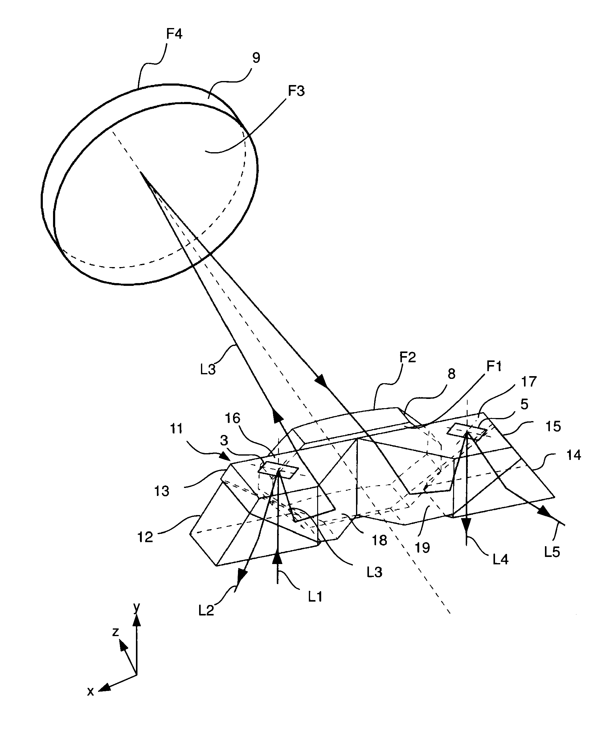
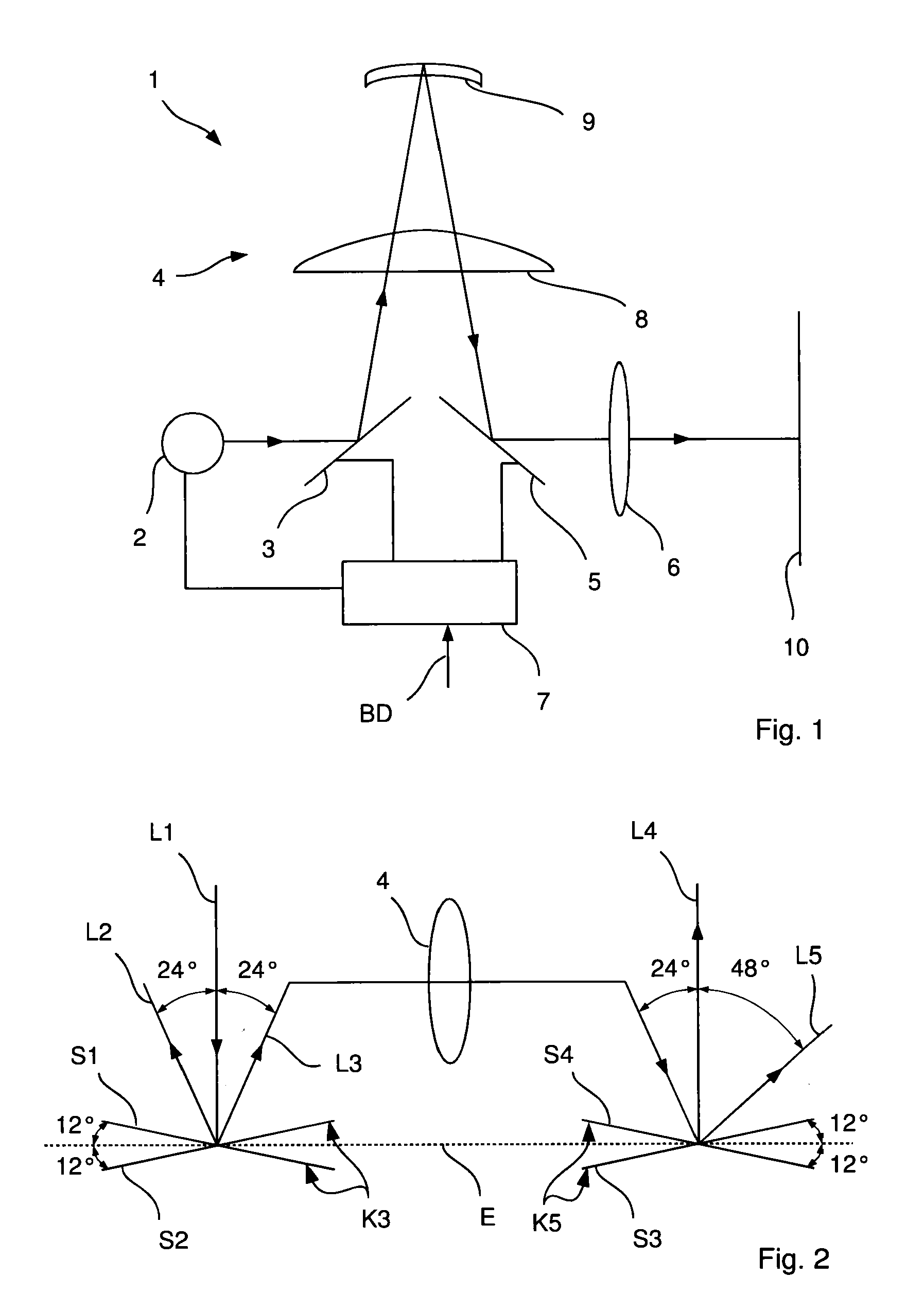
[0087]In the embodiment shown schematically in FIG. 1, the projector 1 according to the invention for projecting an image comprises a light source 2, an illumination modulator 3, imaging optics 4, an image modulator 5, a projection lens system 6 as well as a control unit 7.

[0088]The two modulators 3, 5 are each designed as a tilting mirror matrix having n×m tilting mirrors in columns and rows, wherein the tilting mirrors can, independently of one another, be brought into a first and into a second tilting position.

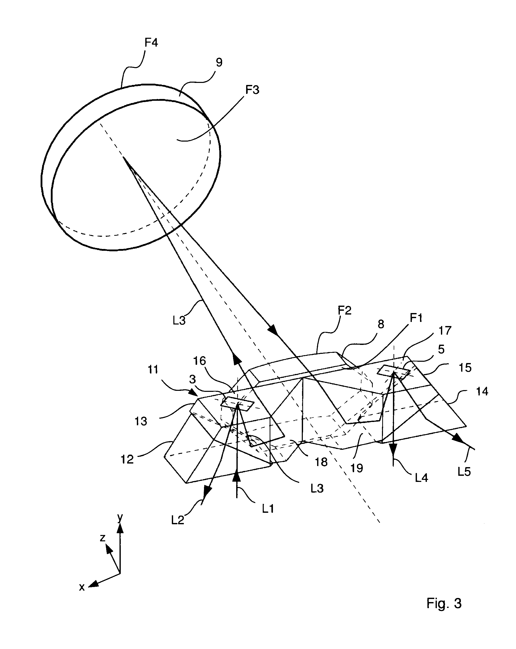
[0089]The imaging optics 4 are designed as 1:1 imaging optics with a first plano-convex lens 8 and a second lens 9 metallized on the back and image each tilting mirror of the illumination modulator 3 precisely onto a tilting mirror of the image modulator 5, with the result that precisely one tilting mirror (hereinafter also called image pixel) of the image modulator 5 is allocated to each tilting mirror (hereinafter also called illumination pixel) of the illumination modula...


PUM


Abstract

A projection system having a first tilting mirror matrix, a second tilting mirror matrix, and an imaging lens, which projects the first tilting mirror matrix onto the second tilting mirror matrix, wherein each tilting mirror matrix has multiple tilting mirrors, the tilting axes of which are positioned in a modulator surface plane. The imaging lens includes a first lens and an imaging mirror, and the imaging mirror forms an aperture stop of the imaging lens, wherein the aperture diaphragm includes an uneven angle of 90° together with the normal of the modulator surface of the first tilting mirror matrix without taking into account any optical path folds.

Description

PRIORITY CLAIM[0001]The present application is a National Phase entry of PCT Application No. PCT / EP2009 / 004531, filed Jun. 23, 2009, which claims priority from German Patent Application Number 102008029785.2, filed Jun. 24, 2008, German Patent Application Number 102008029787.9, filed Jun. 24, 2008, German Patent Application Number 102008029788.7, filed Jun. 24, 2008, German Patent Application Number 102008029789.5, filed Jun. 24, 2008, and U.S. Provisional Application No. 61 / 075,133, filed Jun. 24, 2008, the disclosures of which are hereby incorporated by reference herein in their entirety.FIELD OF THE INVENTION[0002]The present invention relates to a projection system including a first tilting mirror matrix, a second tilting mirror matrix, imaging optics that image the first tilting mirror matrix onto the second tilting mirror matrix; wherein each tilting mirror matrix includes a plurality of tilting mirrors, each tilting mirror having a tilting axis which lies in a modulator surfa...

Claims


Application Information

Patent Timeline
Patent Type & Authority Patents(United States)
IPC IPC(8): G03B21/28
CPCH04N9/3126G03B21/28G03B21/008
Inventor GEISSLER, ENRICONIETEN, CHRISTOPHRUDOLPH, GUENTERPRETORIUS, MARCO
Owner CARL ZEISS JENA GMBH
Why Eureka
Try Eureka