Light-emitting device with high red light brightness and high reliability

A light-emitting device and a technology of a light-emitting layer, which are applied in the direction of optical elements, lighting devices, and components of lighting devices used to change the spectral characteristics of emitted light, can solve high heat, low aluminum reflectivity, red light efficiency and brightness low level problem

Active Publication Date: 2020-07-03
APPOTRONICS CORP LTD
View PDF13 Cites 0 Cited by
  • Summary
  • Abstract
  • Description
  • Claims
  • Application Information

AI Technical Summary

Problems solved by technology

However, aluminum has low reflectivity and high heat generation, so the heat dissipation effect is not good enough
On the other hand, although the reflectivity of the silver reflective layer is relatively high, it is prone to oxidation and vulcanization, so the reliability is low.
In addition, there is also a method of using long-wavelength yellow light combined with a filter to generate red light, in which YAG:Ce with good thermal stability and good light saturation performance is used 3+ For the long-wavelength yellow light of the system, sinc...

Method used


Image

  • Light-emitting device with high red light brightness and high reliability
  • Light-emitting device with high red light brightness and high reliability
  • Light-emitting device with high red light brightness and high reliability

Examples


Embodiment 1

[0052] Embodiment 1 (light-emitting device with fixed red light-emitting module)

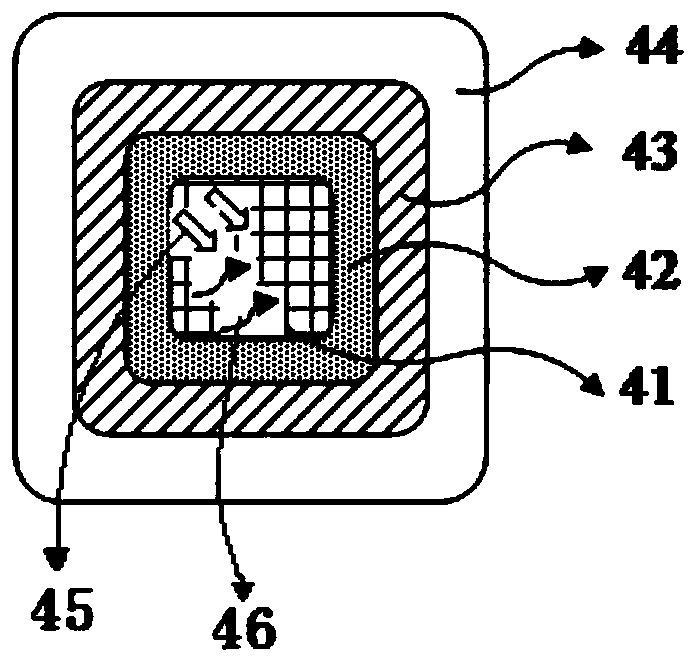
[0053] A schematic diagram of the structure of a light emitting device with a fixed red light emitting module according to Embodiment 1 of the present invention is as follows image 3 As shown, the fixed red light-emitting module of the light-emitting device is composed of a light-emitting layer 41 , a reflective layer 42 , a welding layer 43 and a heat-conducting substrate 44 . The solder layer 43 is disposed on the thermally conductive substrate 44 . The reflective layer 42 is provided on the solder layer 43 . The light emitting layer 41 is provided on the reflective layer 42 . In this embodiment, the luminescent layer 41 is specifically composed of luminescent ceramics as the luminescent part, wherein the luminescent ceramics are preferably Ce 3+ The doping concentration is 1.2mol% of Y 3 Al 5 o 12 Pure phase ceramic or Al 2 o 3 -Y 3 Al 5 o 12 Composite ceramics, or Ce 3+ The dopi...

Embodiment 2

[0056] Embodiment 2 of the present invention (rotary fluorescent color wheel)

[0057] In Embodiment 2 according to the present invention, a rotating fluorescent color wheel is provided, and its structural schematic diagram is as follows Figure 4 As shown, the rotary fluorescent color wheel includes an annular heat-conducting substrate 55, a welding layer 54, a reflective layer (including a red reflective layer 52a, a green reflective layer 52b, a blue reflective layer 52c and a yellow reflective layer 52d arranged coplanarly. ) and light emitting layers (including red light emitting layer 51a, green light emitting layer 51b, blue light emitting layer 51c and yellow light emitting layer 51d arranged coplanarly). The solder layer 54 is disposed on the thermally conductive substrate 55 . The red light reflective layer 52 a , the green light reflective layer 52 b , the blue light reflective layer 52 c and the yellow light reflective layer 52 d are respectively disposed on diffe...


PUM

PropertyMeasurementUnit
Thicknessaaaaaaaaaa
Thicknessaaaaaaaaaa

Abstract

The invention provides a light-emitting device. The light-emitting device comprises a heat conduction substrate, a reflecting layer and a light-emitting layer which are sequentially stacked from bottom to top. The light-emitting device is characterized in that the reflecting layer is a gold reflecting layer, the light-emitting layer comprises any one or more of Y3Al5O12: Ce 3+ fluorescent powder,(Y, Gd)3Al5O12: Ce 3+ fluorescent powder, alpha-SiAlON: Eu 2+ fluorescent powder and (Sr, Ca) AlSiN3: Eu 2+ fluorescent powder, the doping concentration of Ce 3+ in the Y3Al5O12: Ce 3+ fluorescent powder is 1.2mol% or above, the doping concentration of Ce 3+ in the (Y, Gd)3Al5O12: Ce 3+ fluorescent powder is 0.5mol% or above, and the doping concentration of Gd 3+ is 10mol% or above.

Description

technical field [0001] The invention relates to a light emitting device with high red brightness and high reliability. Background technique [0002] At present, it is a conventional technology in the field of laser light sources to irradiate phosphors with lasers to emit light of corresponding colors. We all know that when the laser light source is applied to white light lighting, increasing the red light ratio of the laser light source can improve the color rendering index of the lighting; when the laser light source is used in plant lighting, increasing the red light ratio of the laser light source can be beneficial to photosynthesis Effect and photoperiod effect, the reason is that red light is not only beneficial to the synthesis of plant carbohydrates, but also accelerates the development of long-day plants; and in laser display applications, increasing the proportion of red light in laser light sources can better achieve color reproduction , to solve the problem of re...

Claims


Application Information

Patent Timeline
IPC IPC(8): F21V9/32F21V7/28F21V29/71F21V7/24
CPCF21V9/32F21V7/28F21V29/71F21V7/24H01L25/075
Inventor 田梓峰张世忠李屹
Owner APPOTRONICS CORP LTD
Why Eureka
Try Eureka