High-stability light source system and method of manufacturing
a light source and high-stability technology, applied in the field of light source systems, can solve the problems of general increase in the size and cost of devices, decrease in the output intensities of semiconductor light emitters typically used for this purpose, and decrease in light source stability, so as to minimize the temperature sensitivity of light output and minimize the effect of light output temperature sensitivity
- Summary
- Abstract
- Description
- Claims
- Application Information
AI Technical Summary
Benefits of technology
Problems solved by technology
Method used
Image
Examples
first embodiment
[0157]11) The light-source system is built and the semiconductor light emitter is positioned with its polarization axis relative to the beamsplitter determined by φ0 in a
Design and Adjustment of High-stability Source Made with an Emitter of Unpolarized Light:
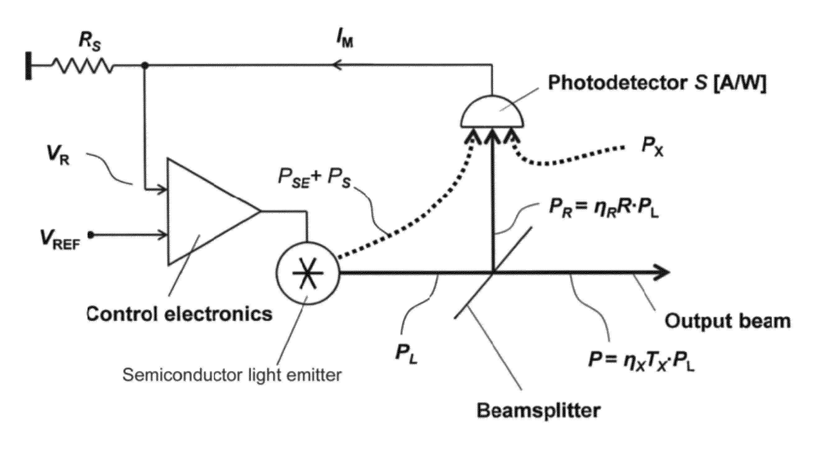
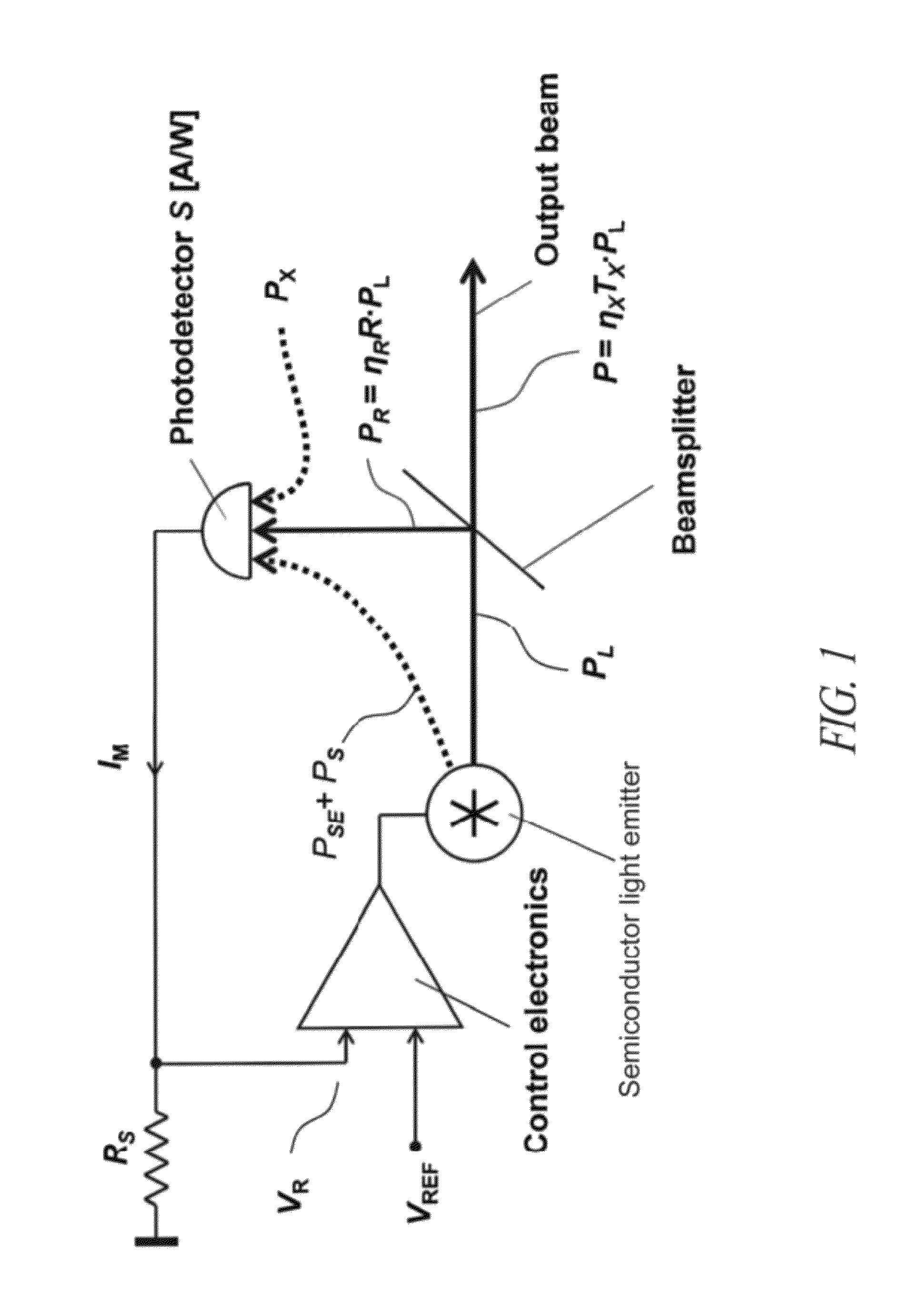
[0158]In another embodiment of the preferred method of high-stability light-source made with an emitter of unpolarized light, a RCLED in exemplary system, is as follows:
[0159]1) The range of peak wavelengths (λMIN and λMAX) and the change in peak wavelength with the temperature of the semiconductor light emitter dλ / dT are measured or obtained from data supplied by the manufacturer for the semiconductor light emitter.
[0160]2) The variation of beam divergence with the temperature and drive current of the semiconductor light emitter are measured or obtained from data supplied by the manufacturer for the semiconductor light emitter.
[0161]3) The wavelength and temperature dependence of the photodetector responsivity, ∂S / ∂λ and ∂S / ∂T,...
second embodiment
[0181]As shown in FIG. 16A a stable light source 30 includes a housing 230 having an emitter cavity 232 with a base 234 comprising a pedestal 236 upon which is mounted a semiconductor light emitter 238 that projects an emitter beam 240 through a first aperture 242. The emitter beam 240 has a divergence angle that contains substantially all of the coherent optical power emitted by the semiconductor light emitter 238. The emitter beam 240 is incident on first collimating lens 244 having first antireflection coating 246 and second antireflection coating 248, which focuses the emitter beam 240 into a collimated beam 250 comprised of light rays that are substantially parallel to one another. The collimated beam 250 is incident upon the first surface 252 of a beamsplitter 254. The beamsplitter 254 is aligned with respect to the emitter beam 240 by a beamsplitter shoulder 256 in a beamsplitter cavity 258. The first surface 252 reflects a portion of the collimated beam 250 to form a reflect...
PUM
| Property | Measurement | Unit |
|---|---|---|
| angles of incidence | aaaaa | aaaaa |
| temperature | aaaaa | aaaaa |
| threshold current | aaaaa | aaaaa |
Abstract
Description
Claims
Application Information
 - R&D
- Intellectual Property
- Life Sciences
- Materials
- Tech Scout
- Unparalleled Data Quality
- Higher Quality Content
- 60% Fewer Hallucinations
Browse by: Latest US Patents, China's latest patents, Technical Efficacy Thesaurus, Application Domain, Technology Topic, Popular Technical Reports.
© 2025 PatSnap. All rights reserved.Legal|Privacy policy|Modern Slavery Act Transparency Statement|Sitemap|About US| Contact US: help@patsnap.com


