Plastic plant pot

Inactive Publication Date: 2013-08-20
POEPPELMANN HLDG GMBH & CO KG
View PDF16 Cites 3 Cited by
  • Summary
  • Abstract
  • Description
  • Claims
  • Application Information

AI Technical Summary

Benefits of technology

[0005]According to the invention this problem is solved by a plant pot with the profile brace, the cupola form can be substantially reinforced and secured against being dented through downwards. Any compression forces on the cupola and the remainder of the floor that appear when plan substrate is put in, when plants are put in or also —more selectively —when tendril sticks and

Problems solved by technology

It is true that the result of this is that when the pot is vigorously filled with substrate and similar material, and also especially when tendril sticks and

Method used


Image

  • Plastic plant pot
  • Plastic plant pot
  • Plastic plant pot

Examples


Embodiment Construction

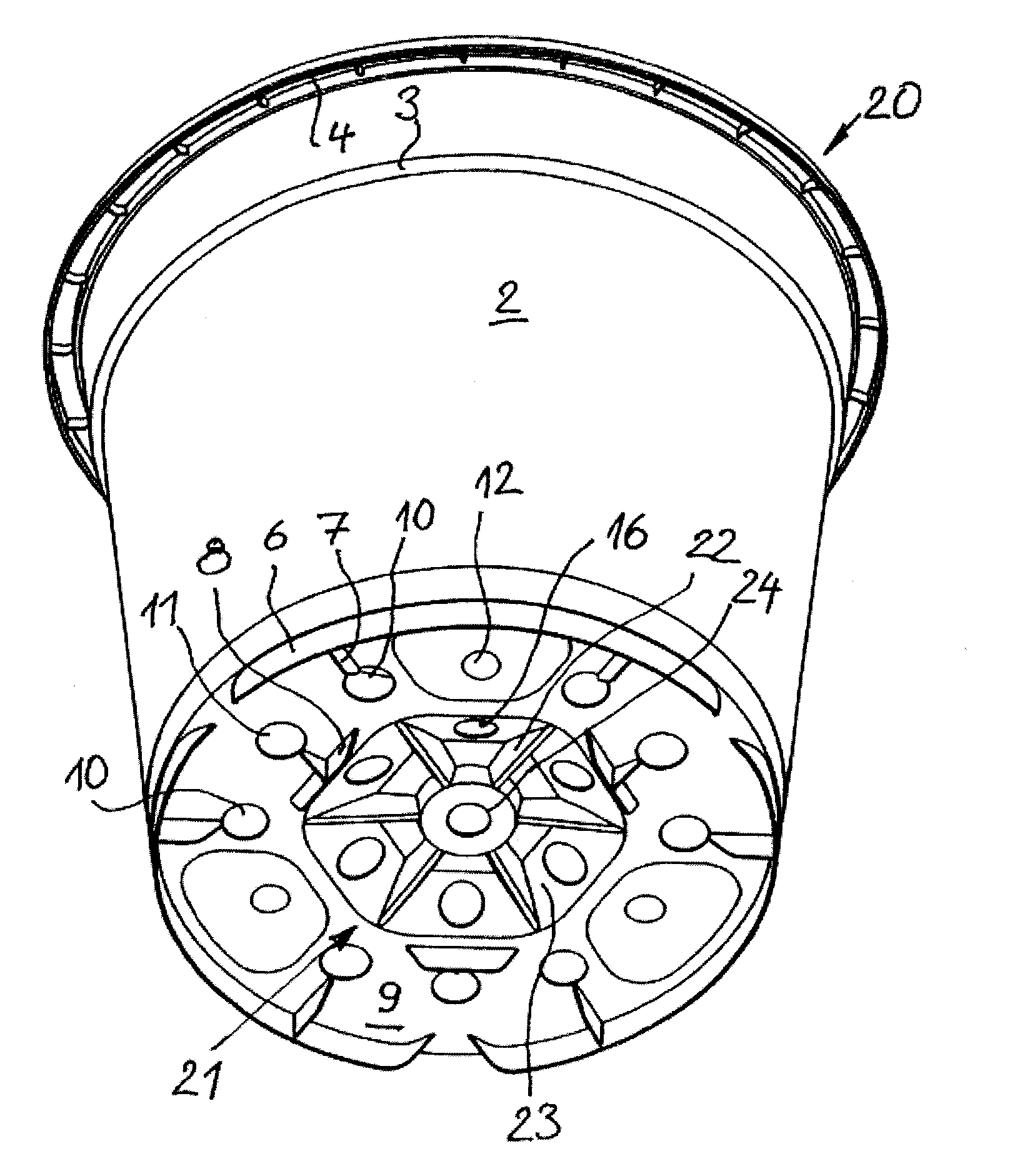
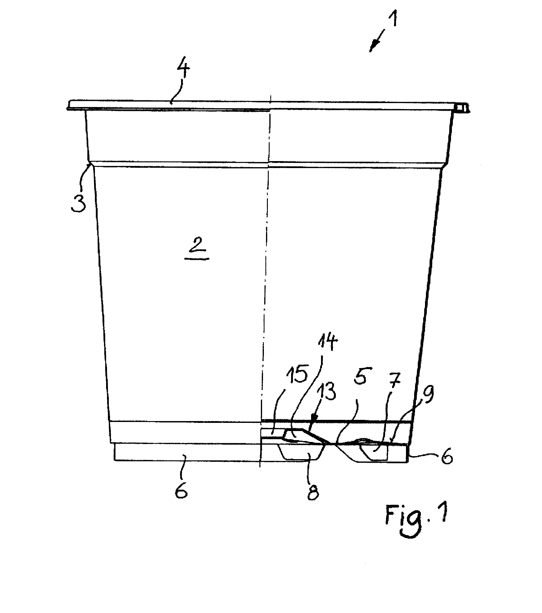
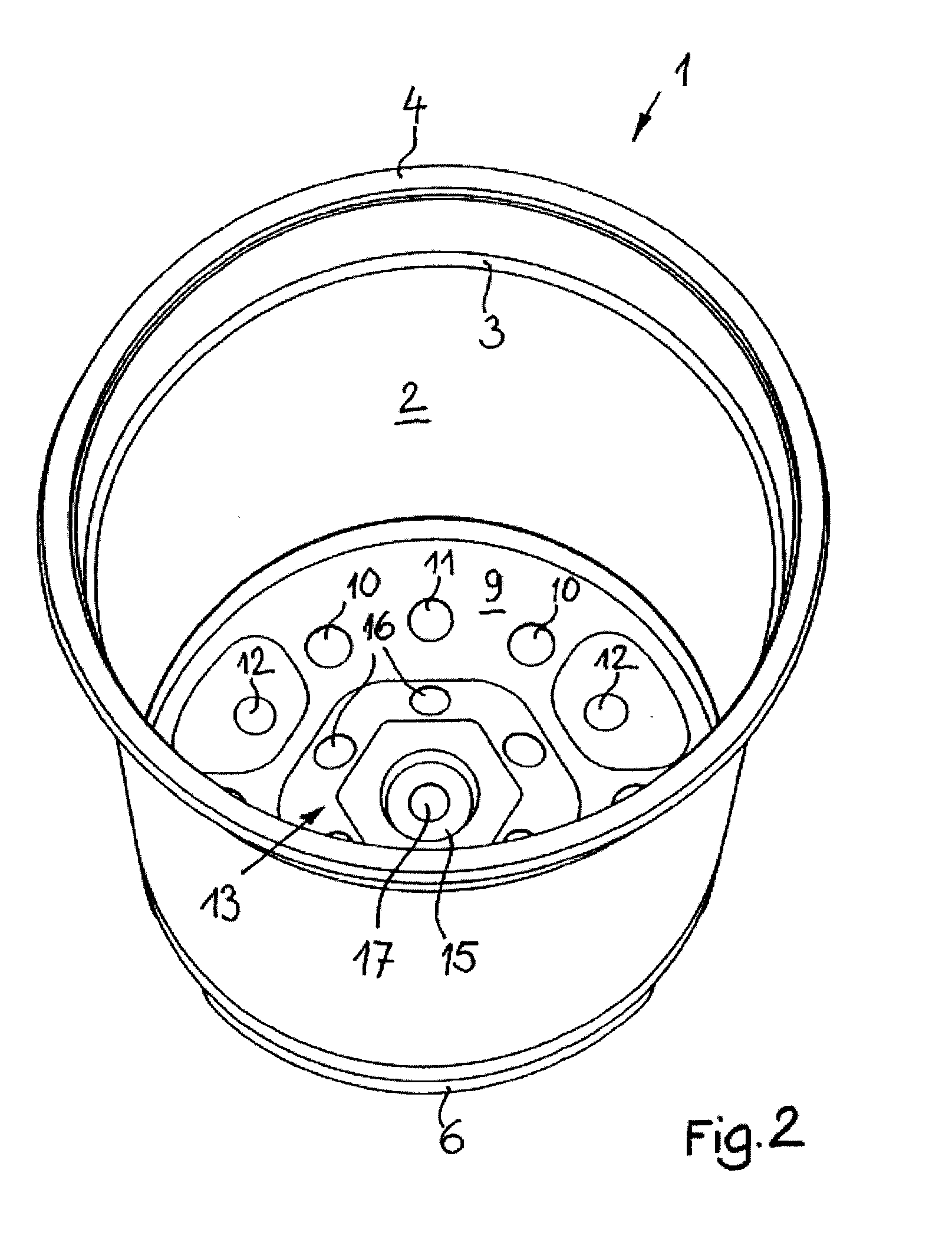
[0020]A plant pot designated overall by 1 in FIGS. 1 to 4 has a customary form in essence shaped like a truncated cone with a wall that is extended upward and is reinforced via a narrow ledge 3 and makes a transition into an edge projecting outwards. On the underside, a bottom 5 is extended via edge ribs 6. Further rib-like projections 7, that are connected at right angles with edge ribs 6, and brace them on the inner side, run predominantly radially beneath bottom 5. T-shaped rib projections are placed beneath a flat peripheral area 9 of bottom 5 as placement feet. As is visible from FIG. 1, the rib projections 8 are designed to be slightly shortened, by which a certain sagging of the bottom is allowed for after the pot is filled, and in any case pot 1 is ensured to sit upright on edge ribs 6. In the flat circumferential area 9, a circular pattern of holes is arranged for water drainage, with ribs 7 and 8 each brought up with slanted drainage edges to holes 10, 11 and 12, to ensure...


PUM


Abstract

A plant pot made of plastic with a predominantly vertically aligned wall and a predominantly horizontally aligned bottom connected on the edge with the wall, which is arched upwards at least in an inner part in the form of a cupola, is configured to secure the bottom area against being compressed through and dented through the material that is as thin-walled as possible, in such a way that the cupola is reinforced by profile braces that run as interties from a central area of the cupola to at least the peripheral areas of the cupola.

Description

FIELD OF THE INVENTION[0001]The invention relates to a plastic pot.BACKGROUND OF THE INVENTION[0002]Plant pots of this type for commercial gardening are generally equipped with a bottom that contains openings for effective water drainage and also when water is supplied temporarily in excess, and on their undersides, with an interval from a placement surface for drainage of water and for ventilation. Surge-watering by means of spraying from above or so-called “ebb-and-flow watering,” in which the plant pots are flushed from time to time from below, first makes provision for water impingement that goes beyond a moisturizing requirement, that reduces drainage of excess water. To avoid waterlogging, especially a water drain on the bottom is to be provided if the plant pot stands on a placement surface that is wetted by water or even provided with water holes. Typically this is to be considered if the plant pots are placed on concrete floors, which form puddles on uneven ground when subj...

Claims


Application Information

Patent Timeline
IPC IPC(8): A01G9/02
CPCA01G9/021
Inventor SCHMIDT, GUIDO
Owner POEPPELMANN HLDG GMBH & CO KG
Why Eureka
Try Eureka