Cupola fairing for an aircraft and method for fabricating the same

A technology for fairings and aircraft, which is applied in aircraft assembly, aircraft parts, fuselage, etc., and can solve problems such as increasing the cross-sectional area

Pending Publication Date: 2020-06-12
AERO DESIGN LABS INC
View PDF10 Cites 1 Cited by
  • Summary
  • Abstract
  • Description
  • Claims
  • Application Information

AI Technical Summary

Problems solved by technology

This practice sometimes increases the cross-sectional area of ​​the fuselage ahead and behind where the wings meet

Method used


Image

  • Cupola fairing for an aircraft and method for fabricating the same
  • Cupola fairing for an aircraft and method for fabricating the same
  • Cupola fairing for an aircraft and method for fabricating the same

Examples


Embodiment Construction

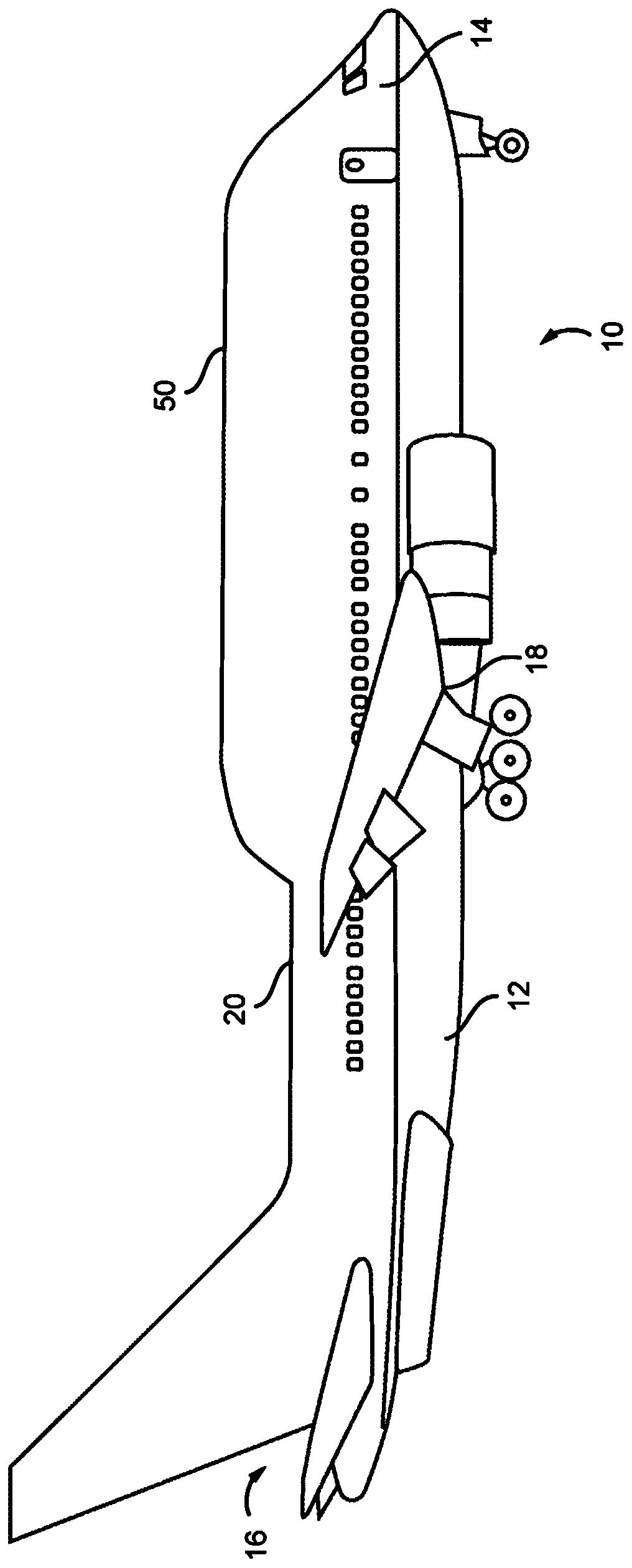
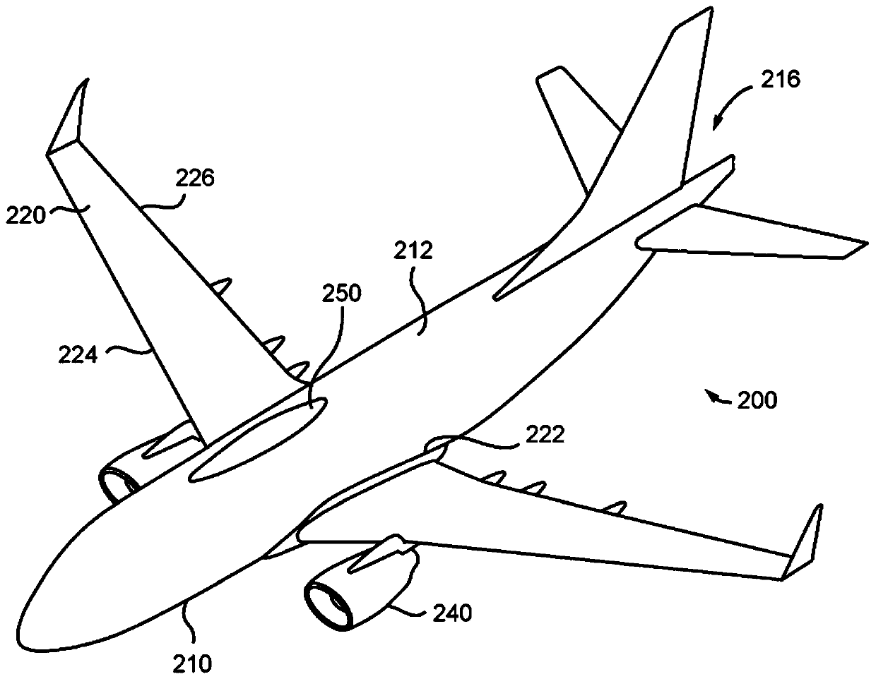
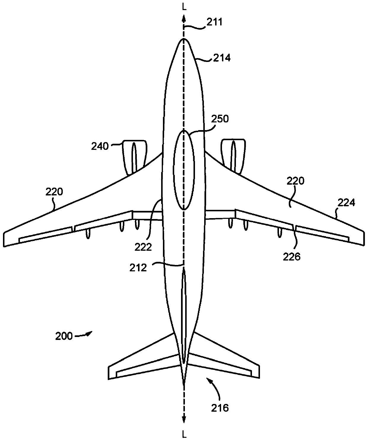
[0049] The invention relates to a dome fairing positioned on the top portion of an aircraft fuselage. the dome fairing is sized and dimensioned to fit over the top portion of the fuselage and to extend longitudinally along the fuselage at a spanwise location near between the wings of the aircraft to optimize airflow around the fuselage, This makes the airflow straighter along the wing at the root of the wing. In particular, domed fairings help reduce drag on parts of the aircraft, thereby increasing fuselage lift and spanwise (wingtip to wingtip) lift, making it more nearly elliptical. Other advantages include reduced leading edge stagnation drag and trailing edge separation drag, as well as reduced wing-to-fuselage and fuselage-to-wing swirl and associated drag.

[0050] Furthermore, a reduction in drag in other regions of the fuselage can be achieved. These modifications may be specific to the aircraft configuration, for example, tail effects are different on conventional ...


PUM


Abstract

A cupola fairing (250) for reducing drag and increasing lift on an aircraft fuselage (210) and wings (220). The fairing includes a housing length extending along a longitudinal axis, and a variable width extending normal to the longitudinal axis. The housing width is variable and defined by a plurality of cross-sectional areas of the cupola fairing. The fairing has a substantially smooth exteriorsurface that is curved along the length and the variable width of the housing. The housing surface has its longitudinal and transverse curvatures being defined by metrics corresponding to a referencewing root chord of the aircraft (200), a cross-sectional area of the fuselage, a percentage of the cross-sectional area to be covered by the fairing, and positioning of the cupola fairing on the crownportion of the fuselage (210). The housing has a lower surface configured to conform to a shape of the crown at which the cupola fairing (250) is positioned.

Description

[0001] Cross References to Related Applications [0002] This patent application claims priority to U.S. Provisional Application No. 62 / 560,982, filed September 20, 2017, the entire contents of which are incorporated herein by reference. technical field [0003] The present invention relates to aircraft fairings, and more particularly to dome fairings on aircraft. Background technique [0004] Most practical and successful personal, commercial, and military transport aircraft include combined designs with wing aspect ratios greater than 5:1 and fuselage slender ratios greater than 6:1. All of these successful transport vehicles were of what the industry considers a conventional configuration, with a generally tubular fuselage, a single high-aspect-ratio lift wing located near the vehicle's center of gravity, and a negative-lift horizontal tail. These designs include high-wing configurations for military transports and some small commercial transports, and low-wing configura...

Claims


Application Information

Patent Timeline
Patent Type & Authority Applications(China)
IPC IPC(8): B64C1/00B64C1/38B64C7/00B64F5/10
CPCB64C1/0009B64C1/38B64C7/00B64F5/00B64C2001/0045Y02T50/10B64F5/10
Inventor 埃里克·A·阿尔斯特伦
Owner AERO DESIGN LABS INC
Why Eureka
Try Eureka